News
Shepard Test Stand: Shepard v1.1 Dev Log (Temperature DAQ) Started: 05-21-13 (27 comments)
I had to wait awhile to go get parts to mount the load cell on the v1.1 structure, so I started to research communicating with the ADS1118 via an Arduino to get the thermocouple data.
I found this blog post which at least shows how to get a single ended voltage (single shot, high speed). I then got the register settings for temperature monitoring from this source .
Using these resources, I came up with the following simple source code for the Arduino:
#include <SPI.h>

void setup() {
  Serial.begin(9600);

  // Set up and start the SPI serial interface
  SPI.begin();
  SPI.setBitOrder(MSBFIRST); // Most significant bit first
  SPI.setClockDivider(SPI_CLOCK_DIV8); // Step down the arduino clock by 8
  SPI.setDataMode(SPI_MODE1); //Serial interface timing
}

void loop()
{
  Serial.println(readRaw());
  delay(1000);
}

/* Allows the caller to read the raw value from the ADS1118 */
int readRaw(void) {
  int rawValue; // Raw value received back from the ADS1118
  byte MSB, LSB; //The most and least significant bits read from the ADS1118
  byte MSBConf=B10001011; // Most Significant Bit configuration register
  //11010001
  byte LSBConf=B11110010; // Least Significant Bit configuration register
  //10000010

  // Read the ADS1118's channel's A0 and A1 as temperature in single-shot mode
  MSB = SPI.transfer(MSBConf);
  LSB = SPI.transfer(LSBConf);
  //SPI.transfer(MSBConf);
  //SPI.transfer(LSBConf);

  // Build the raw value from the most and least significant bits
  rawValue = (MSB << 8) | LSB;

  return rawValue;
}

/* Allows the caller to read the raw voltage */
double readVoltage(void) {
  int rawValue; // Raw value received back from the ADS1118
  double volts; // Converted voltage from the raw value
  const double amp = 0.256; // FS multiplier in register (check data sheet)

  // Get the raw value so that we can convert it to a voltage
  rawValue = readRaw();

  // Convert the raw value to the corresponding voltage (16 bits = 0 to 32767)
  volts = amp * (double)(rawValue / 32768);

  return volts;
}
Using the following resources, I then came up with the circuit below:
Fritzing Diagram
( Large ) ( Real Life Breadboard Photo )
The blue terminal block on the breadboard is what the thermocouple leads attach to.
Fritzing Generated Schematic
( Large )
The two open terminals on AIN0 and AIN1 represent the attachment points for the thermocouple leads.
For anyone reading this after the fact, keep in mind that this was my first time using Fritzing and I did a horrible job of routing. I really like Fritzing so far though.
When I tested the ADS1118 circuit with the source code above, I found that it wouldn't display any value except -1. I'm not sure yet what is causing this problem. If anyone reading this figures it out before I do, please feel free to leave a comment and let me know.
DMX Gizmo: Project is in progress. (4 comments)
The project is currently at version 0.1 and running well. Currently the device has direct control over a full universe of DMX, allowing active modification of a single channel's value at a time. The interface is basic, allowing an arbitrary level to be set, for the active channel to be directly set to full or zero, or allowing all channels to be released. There's also a clear button in the event of incorrect values, and input sanitation to prevent impossible values from being entered.

https://www.youtube.com/watch?v=8oGVmMjnNsI
https://www.youtube.com/watch?v=x4itowiFaRY
The hardware currently consists of an Arduino, an off-the-shelf DMX shield from Tinkerkits, a 4x4 keypad and a 16x2 serial LCD.
The current state of the project is pretty far from where I hope to end up, but it's going to be a journey. Ultimately the device will likely be running on a Raspberry Pi or similar ARM-based single-core computer, with a user interface written in Python or Processing, but until I actually hit the limits of the Arduino I'd like to see how far I can get.
Next steps, currently, are interface design. There are a few more basic features (next/last channel, 5% up/down buttons, some way to view active channels) that need to be implemented. I'll need to locate a graphical LCD (I'm thinking about perhaps trying one of those 1.8" LCDs) that's suitable, and figure out how to design a UI.
Thanks for reading,
Derek
Shepard Test Stand: Shepard v1.1 Dev Log (Thrust DAQ) Started: 05-20-13 (46 comments)
The DAQ (Data AcQuisition) system for version 1.1 of the Shepard Test Stand is quickly getting left behind technology-wise. We believe that we've found a good source for small load cells, which makes the use of FSRs (Force Sensing Resistors) not worth pursuing any more. The sample rate due to the thermocouple amplifier is far too slow as well, and we're looking at switching to a non-contact temperature sensor to obtain faster sensor response during runs. However, we still have a partner organization that needs a version of Shepard to experiment with, pre-2.0, and I thought that I'd use a hybrid platform of the old and the new technologies to test out some of our ideas in version 1.1. Hopefully I'll end up with a setup that our partner can utilize for their testing that will also be a good test bed for our new components.
The two ICs in this test circuit are the INA122 Instrumentation Amplifier , and the ADS1118 amplifier/ADC , set up to amplify thermocouple inputs. The ADS1118 required a MSOP10 to DIP converter so that I could use it with a breadboard/protoboard. Thanks to Aaron Harper for going through the painstaking process of soldering/reflowing such a small package for me.
I'll start with the INA122, although both ICs will be on the breadboard so that I can plan the layout appropriately.
Using the following resources, I came up with the circuit below:
- http://www.ti.com/lit/ds/sbos069/sbos069.pdf
- http://www.nakka-rocketry.net/strainlc.html
- http://www.nerdkits.com/videos/weighscale/
- http://www.robotshop.com/phidgetbridge-wheatstone-bridge-sensor-interface-2.html (Documentation link)
( Large )
It made sense to me that for testing purposes, the gain of the INA122 should be adjustable, so I swapped out the 1k RG fixed resistor for a 10k 15-turn potentiometer. I then experimented with the gains shown in the INA122's application information. I found that the gains of 1000 (200 ohms) to 5000 (40.2 ohms) gave a good amount of change with the force that I applied with my fingers. The next step was to clamp the load cell down to my desktop and hang some weight from it, using a hanging scale for reference.
( Large )
The max thrust we should ever see from an Estes motor (A through E) on Shepard is around 30 Newtons (6.74 lbs). If we want to calibrate to 1.4 times the max thrust we'll ever see (per good engineering practices), we'll need to calibrate to 42 Newtons (9.44 lbs). I thought that I'd go ahead and round that value up to set the gain so that 9.5 lbs was the max, or would "fill" the Arduino's ADC. I started to use jugs of water to reach this weight (simulated thrust). Unfortunately, I didn't have the right kind of clamps to hold one end of the load cell properly. I believe my best bet of getting the gain set and calibrating the load cell will be to make the minor modifications necessary to mount the load cell in the Shepard v1.1 structure used during Yuri's Night (starts at about 1:03:19). Then I can use the previous calibration mechanism (pulley and string) to set and calibrate the system.
Thoughts, questions, suggestions? Feel free to leave them as comments on this news feed.
Shepard Test Stand: Shepard v1.1 Dev Log (DAQ) 04-03-13 (5 comments)
The first thing following from yesterday's work was to determine the maximum voltage coming from the FSR's output at a target weight, so that I could build a voltage divider to feed that voltage to the AREF pin on the Arduino.
I used a multimeter and measured between the output (yellow wire in yesterday's pic) and ground (green) to get this voltage. The absolute max that I was able to get out of the FSR's voltage divider with the variable resistor set to approximately 100k-Ohm was about 4.0 volts (with 5 volt supply from the Arduino). This would represent the maximum force for the FSR, which is 25 lbs (110 N). The maximum thrust that we expect to see from the Estes motors used with Shepard will be 30 N (6.7 lbs). Assuming that we want to calibrate to at least 1.4 times the maximum expected value (good engineering practice), the FSR range needs to be set to max out somewhere around 41.8 N (9.4 lbs).
I don't have the means to add this amount of weight to the sensor right now, but I do have access to a gallon jug and water (about 8.3 to 8.5 lbs). This will give me a relatively known weight to experiment with.
The jug of water's weight gave me about 2.6 volts, and if I work that out based on a max of 4.0 volts at 25 lbs I get:
2.6 volts / x lbs = 4.0 volts / 25 lbs
which becomes:
2.6 volts * 25 lbs = 4.0 volts * x lbs
which becomes:
x = (2.6 volts * 25 lbs) / 4.0 volts
or
x = 16.25 lbs
Obviously, 16.25 lbs a little less than twice the value I should get. It's getting late where I'm at, so I'll figure out what I did wrong tomorrow evening.
For anyone reading this dev log in the meantime, I'd welcome your help. Did I make a simple mistake (very likely at this hour of the night)? Is there a fundamental flaw in the way I've built the circuit? Is there something else going on? Let me know in a comment to this news item.
Shepard Test Stand: Shepard v1.1 Dev Log (DAQ) 04-02-13 (2 comments)
It occurred to me that the Shepard 1.0 DAQ software has not been milestoned and added to DMSF yet. I've already shipped the 1.0 DAQ shield for the Arduino to J for the Yuri's Night demos, so he's going to test the version in the repo out. Once it's confirmed that works, I'll zip the code up for upload to DMSF as the 1.0 milestone version. For now, I'll keep my changes local.
The new thrust measurement circuitry for the DAQ system has been prototyped, and seems to work well.
It uses a higher quality FSR ("Force Sensing Resistor" that costs about $25), and uses a variable resistor to set the effective range of the FSR (Flexiforce Sensor). The variable resistor's max is 100k-Ohm since this is the max specified in the FSR's documentation. In order to see and adjust this range, you can use the "Raw Value" field of the Calibration_Util_Processing.pde Processing app. The process for setting the max range is below, and is a rough cut at creating a max range setting process.
1. Add the amount of weight onto the FSR that represents the max that you ever want the sensor to be able to read (up to the 25 lb max).
2. Adjust the variable resistor until the "Raw Value" reading is maxed out at that weight (~1023 if possible).
3. Put a dot of clear silicone (RTV) on the side of the resistor where the "turntable" and the body meet. This will prevent the resistor from turning on its own during a rough shipping trip.
While working on this I was reminded that the default reference voltage for the Arduino's ADC is 5.0 volts. Since the FSR is being used in a voltage divider that's being fed from the Arduino's 5V pin, this means that we'll never "fill" the ADC's range, and thus we won't have the maximum resolution possible. This can be corrected by building a voltage divider and using it to feed the AREF (external ADC reference voltage) pin with the max voltage that we ever expect seeing from the FSR's voltage divider.
Scanning Tunnelling Microscope: Rev B design of bias voltage amplifier complete (2 comments)
The new bias voltage amplifier design (redone as a simple differential input amplifier) is complete. PCB fabrication is underway and design files are in repository.

Scanning Tunnelling Microscope: Tunnelling current amplifier PCB layout complete (2 comments)
The new differential output amplifier layout is done, and the team at OSH Park are fabricating the board. The design files, including parts list, have been uploaded to the repository.
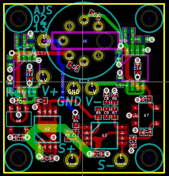
While I'm waiting for the PCB to arrive, I will proceed with the redesign of the bias amplifier to use a differential input.
Scanning Tunnelling Microscope: Tunnelling current amplifier redesign (3 comments)
After discovering the LT6350 single-ended to differential voltage converter IC, I decided to convert the tunnelling current amplifier to differential output. This should improve noise immunity, which is crucial since I intend using an 18-bit A/D converter to digitise this signal at the main controller. I have further decided to omit the high-frequency signal recovery section of the amplifier and implement this functionality in firmware (assuming adequate performance from the A/D). This simplifies the amplifier and reduces the amount of 'hand tweaking' of the amplifier response.
I may also convert the bias voltage controller to differential (differential output from the main controller, converted to single-ended at the STM). This should reduce the susceptibility of the bias voltage to external noise pickup, and by moving the D/A converter to the main controller, reduce by 3 the number of wires going to the STM.

AttenuatorX: XTest1 Schematic nearly complete
XTest1 is the first of two test stages, prior to completing the design of AttenuatorX. The initial schematic has just been completed and annotated. The project is being developed using KiCad.
Open Design Engine: Public Beta is here!!! (5 comments)
With the help of Kevin Bouwkamp, Bryan Christian, and The School Factory, we have reached a critical milestone: The Public Beta of ODE. Self-registration for user accounts is now active, and we are ready for our next round of promotion of Open Design Engine. Please share the news on Twitter, Facebook, Google+, and your own personal blogs (be sure to link to this page). And, if you have not signed up for an account yet, please do so. Then, start a project on ODE and document one of your Open Source Hardware projects (or document a new one from day one).
And this is just the beginning. We are actively improving the site. For example, just this weekend Kevin completed the funding plugin, allowing users to insert Kickstarter badges and Paypal buttons into any field which supports wiki-syntax (this is in addition to earlier support developed by Littlelines which enabled users to insert Pledgie and ChipIn badges). Future plans include adding support for integrated git repositories and major improvements to the user interface. As always, watch the roadmap to keep up with our plans and progress.
Thanks to all of our supporters, backers, and volunteers. We are looking forward to growing Open Design Engine into a great site for hosting open source hardware projects. And remember, Makers, document what you make.
« Previous 1 ... 6 7 8 9 10 11 Next »
Also available in: Atom