« Previous -
Version 7/10
(diff) -
Next » -
Current version
J. Simmons, 06/23/2018 06:42 pm
Controller Assembly
Tools
- Holoseat Test Stand with computer to operate it
- Soldering iron with stand
- Helping hands
- Exhaust fan
- Flush snips
- Safety glasses
Materials
- Instant/super glue (prefer Loctite Super Glue Ultragel Control)
- Solder
- (1) HSC-01: Feather
- (1) HSC-02: Holoseat Controller Wing
- (1) HSC-03: Controller Housing Base
- (1) HSC-04: Controller Housing Top
- (1) HSC-05: 12 pin header
- (1) HSC-06: 16 pin header
- (1) HSC-07: Holoseat Custom Key Cap
- (1) HSC-08: TRRS Wing
- (1) HSC-09: Keyswitch
- (1) HSC-10: Controller Housing Mounting Slot
Safety Issues
- Care must be taken when using the soldering iron, the tip is very hot
- Always wear safety glasses while working with soldering irons
- Avoid breathing in the soldering fumes, use a vent or hood if needed to provide adequate ventilation
Product
HS-02: Controller
Procedure
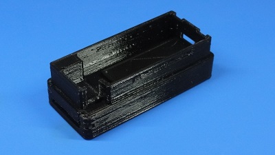
1. Prepare Mounting Slot
- Do a test fit (without glue) of the HSC-03: Controller Housing Base and HSC-10: Controller Housing Mounting Slot by sliding the Controller Housing Base into the Controller Housing Mounting Slot
Insert Pic - Separate the Controller Housing Base into the Controller Housing Mounting Slot
- Apply super glue to the inner perimeter of the Controller Housing Mounting Slot where the Controller Housing Base will sit, taking care to keep glue out of the cut out for the slot; apply extra super glue to the large raised surface to ensure a strong bond
Insert Pic - Slide the Controller Housing Base into the Controller Housing Mounting Slot and press the pieces together per the glue's instructions (typically 1 minute)
- Allow the glue to cure per its instructions
2. Solder Headers to Feather
TBD by Bryan
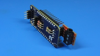
3. Assemble Controller Components
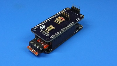
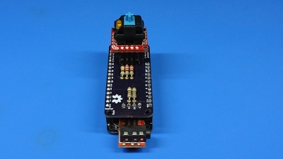
- Attach HSC-08: TRRS Wing to underside headers on HSC-02: Holoseat Controller Wing
Insert pic - Attach TRRS Wing + Controller Wing to Feather
Insert pic - Attach HSC-09: Keyswitch to Controller Wing (note, the LED on the Keyswitch should be on the left side when the TRRS Wing is toward you)
Insert pic
4. Test Controller
TBD by J. when test and firmware code is updated
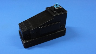
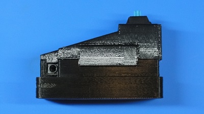
5. Final Assembly
- Insert Feather + Wings into HSC-03: Controller Housing Base
Insert Pic - Attach HSC-04: Controller Housing Top onto Controller Housing Base making sure the snap fit connection fully clicks and the inset over TRRS connector seats fully into the Controller Housing Base
Insert Pic - Attach HSC-07: Holoseat Custom Key Cap to Keyswitch
Insert Pic