« Previous -
Version 4/41
(diff) -
Next » -
Current version
J. Simmons, 09/22/2013 10:43 pm
Assembly Instructions
- Assembly Instructions
- Step 0 - Acquire the parts of the v0.2 Holoseat
- Step 1 - Attach the mini-breadboard (HS011) to the protoshield (HS002)
- Step 2 - Attach protoshield (HS002) to the Arduino Leonardo (HS001)
- Step 3 - Wire ground pin and 5v pin to separate rows on mini-breadboard
- Step 4 - Attach lead wires to the reed switch (HS003)
- Step 5 - Attach the reed switch (HS003) to the exercise equipment
- Step 6 - Attach magnet from reed switch (HS003) to the exercise equipment
- Step 7 - Wire the reed switch (HS003) to the mini-breadboard (HS011)
Below are the assembly instructions for the v0.2 Holoseat controller. Remember, this is a breadboard level prototype. While it is fully functional, the lack of permanent solder joints makes it unsuitable for long term use in the "real world". If you want a permanent version, consider skipping the mini-breadboard and soldering the components directly onto the prototype board.
Step 0 - Acquire the parts of the v0.2 Holoseat
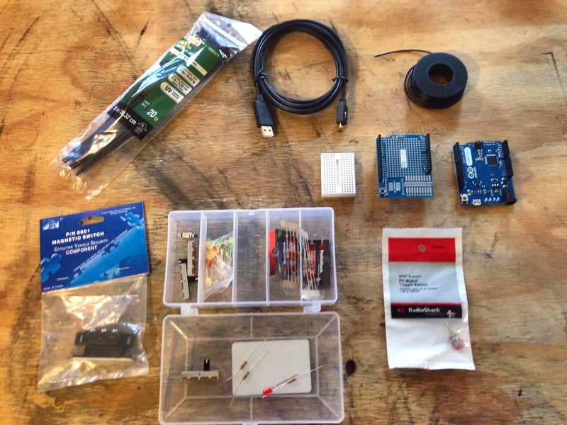
See the Bill of Materials for complete list of components.
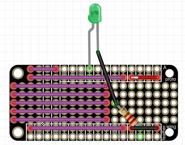
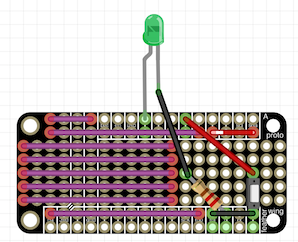
Step 1 - Attach the mini-breadboard (HS011) to the protoshield (HS002)

Peel the backing paper off of the mini-breadboard and place as shown. Make sure not to cover the pin labels on either row of headers (the pin labels for the lower row of pin headers are covered in the photo above).
Step 2 - Attach protoshield (HS002) to the Arduino Leonardo (HS001)

Make sure the pins line up and gently but firmly press the protoshield down until it stops. The pins will still be showing as can be seen in the photo.
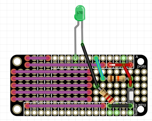
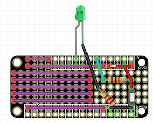
Step 3 - Wire ground pin and 5v pin to separate rows on mini-breadboard

The lower row is wired to the ground pin, the upper row is wired to the 5v pin.
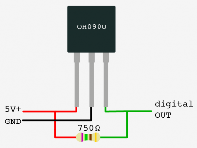
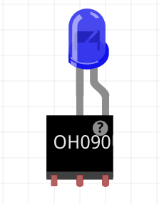
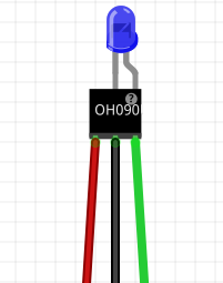
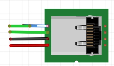
Step 4 - Attach lead wires to the reed switch (HS003)

Make sure one lead is attached to the common terminal (COM) and the other is attached to the normally open (NO) terminal.
Step 5 - Attach the reed switch (HS003) to the exercise equipment

Use the adhesive backing and zip ties (HS006) to ensure the reed switch is secure.
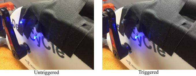
Step 6 - Attach magnet from reed switch (HS003) to the exercise equipment

Use zip ties (HS006) to attach the magnet on the pedal or similar part if the exercise equipment. Note, the prototype's reed switch comes with a very weak magnet, so there is some foam bring used as a spacer to ensure the magnet is close enough to trigger the reed switch. You can test it using a multimeter to detect continuity as the pedal passes the reed switch.
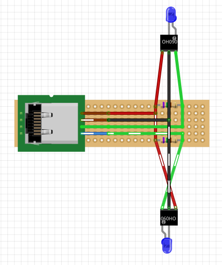
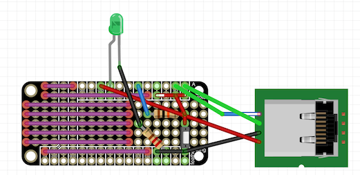
Step 7 - Wire the reed switch (HS003) to the mini-breadboard (HS011)

Refer to the Detailed Design for more information on how to wire the reed switch to the Holoseat.