« Previous -
Version 2/41
(diff) -
Next » -
Current version
J. Simmons, 09/22/2013 10:35 pm
Assembly Instructions
Below are the assembly instructions for the v0.2 Holoseat controller. Remember, this is a breadboard level prototype. While it is fully functional, the lack of permanent solder joints makes it unsuitable for long term use in the "real world". If you want a permanent version, consider skipping the mini-breadboard and soldering the components directly onto the prototype board.
Step 0 - Acquire the parts of the v0.2 Holoseat
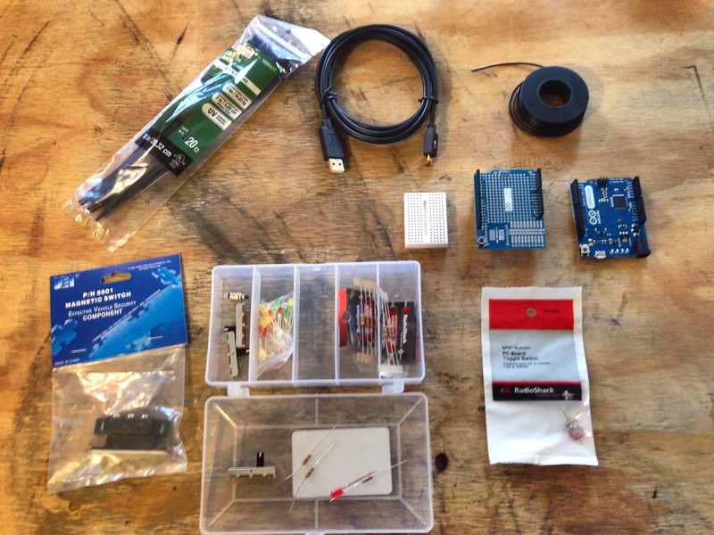
See the Bill of Materials for complete list of components.
Step 1 - Attach the mini-breadboard (HS011) to the protoshield (HS002)

Peel the backing paper off of the mini-breadboard and place as shown. Make sure not to cover the pin labels on either row of headers (the pin labels for the lower row of pin headers are covered in the photo above).
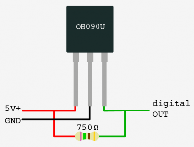
0h090u1-400x302.png
(54.4 kB)
J. Simmons, 07/17/2016 03:37 pm
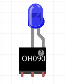
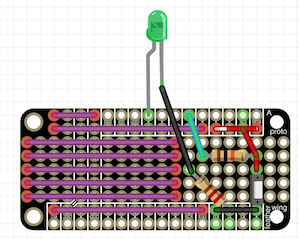
led-plus-sensor.png
(16.9 kB)
J. Simmons, 07/17/2016 03:37 pm
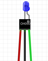
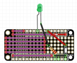
led-plus-sensor-and-leads.png
(15.8 kB)
J. Simmons, 07/17/2016 03:56 pm
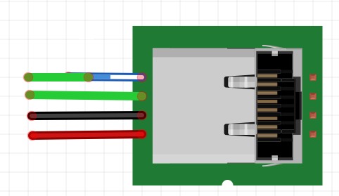
cat5e-jack-with-leads.png
(13.7 kB)
J. Simmons, 07/17/2016 04:15 pm
sensor-board.png
(45.3 kB)
J. Simmons, 07/17/2016 04:25 pm
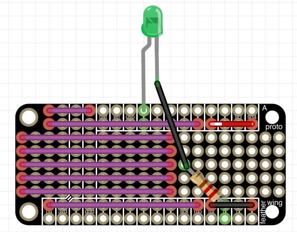
led-on-feather.png
(70.7 kB)
J. Simmons, 08/14/2016 03:31 pm
switch-connected-to-feather.png
(80.3 kB)
J. Simmons, 08/14/2016 03:53 pm
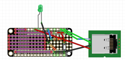
cat5e-jack2-with-leads.png
(22.9 kB)
J. Simmons, 08/14/2016 03:53 pm
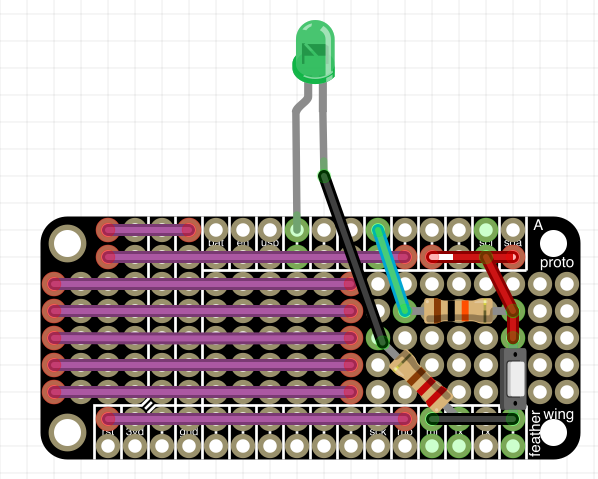
completed-controller.png
(113.9 kB)
J. Simmons, 08/14/2016 04:03 pm
cat5e-jack2-with-leads.png
(24.3 kB)
J. Simmons, 08/14/2016 04:06 pm
completed-controller.png
(102 kB)
J. Simmons, 08/14/2016 04:07 pm
led-on-feather.png
(84.4 kB)
J. Simmons, 08/14/2016 04:07 pm
switch-connected-to-feather.png
(76.3 kB)
J. Simmons, 08/14/2016 04:07 pm
switch-connected-to-feather.png
(63.9 kB)
J. Simmons, 08/14/2016 07:28 pm
completed-controller.png
(122.7 kB)
J. Simmons, 08/14/2016 07:28 pm
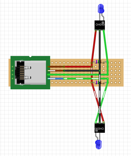
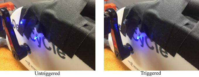
SensorLights.png
(289 kB)
J. Simmons, 12/22/2016 04:47 pm
Also available in:
HTML
TXT