« Previous -
Version 12/24
(diff) -
Next » -
Current version
J. Simmons, 12/26/2017 06:09 pm
Assembly Instructions
Introduction
TBD
Test Stand Body Assembly
Tools - Test Stand Body
- Mitre Saw (preferably powered)
- Pencil
- Carpentry square
- Tape Measure
- Screw Gun
- 1/16" Drill bit (for TS-07: 1-1/4" Fine Thread Drywall Screws)
- 1/8" Drill bit (for TSB-03:
#9x 2-1/2" Coarse Thread Drywall Screws) - Phillips screw driving bit
- (2) 12" (or larger) Bar clamps
- Sand paper
- Paint brush
- Painter's Tape
- Rags
Materials - Test Stand Body
- (2) TSB-01: Side Boards
- (2) TSB-02: Top Boards
- (6) TSB-03:
#9x 2-1/2" Coarse Thread Drywall Screws - (1) TSB-04: 36" Long 2x3 Board
- (1) TS-06: Nema 17 Stepper Motor Mount
- (4) TS-07: 1-1/4" Fine Thread Drywall Screws
- TSB-05: Semi-gloss latex paint
Safety Issues - Test Stand Body
- Always wear safety glasses when working with carpentry tools
- Take care when using saws (especially power saws)
Product - Test Stand Body
(1) TS-01: Holoseat Test Stand Body
Procedure - Test Stand Body
- Produce Side and Top Boards
- Use a miter saw to cut (2) 12" long boards from TSB-04: 36" Long 2x3 Board to produce (2) TSB-01: Side Boards
(also requires tape measure, carpentry square, and pencil) - Use a miter saw to cut (2) 5" long boards from TSB-04: 36" Long 2x3 Board to produce (2) TSB-02: Top Boards
(also requires tape measure, carpentry square, and pencil)
- Use a miter saw to cut (2) 12" long boards from TSB-04: 36" Long 2x3 Board to produce (2) TSB-01: Side Boards
- Assemble the TS-01: Holoseat Test Stand Body
- Use the bar clamps to secure (1) TSB-01: Side Boards and (1) TSB-02: Top Boards in a butt joint flush with the edge of the side board and with their ends aligned
- Drill (2) 1/8" pilot holes through the face of the side board and into the edge of the top board
- Use (2) TSB-03:
#9x 2-1/2" Coarse Thread Drywall Screws to secure the side board to the top board - Repeat the past 3 steps to attach the other TSB-02: Top Boards to the side board making sure the gap between the top boards is wide enough for the TS-06: Nema 17 Stepper Motor Mount
INSERT PIC HERE - Place the TS-06: Nema 17 Stepper Motor Mount against the face of the side board between the top boards
- Drill (4) 1/16" pilot holes into the face of the side board
- Use (4) TS-07: 1-1/4" Fine Thread Drywall Screws to attach the motor mount to the side board making sure its top is flush with the top face of the top boards
INSERT PIC HERE - Use the bar clamps to secure the other TSB-01: Side Boards to the opposite side of the (2) TSB-02: Top Boards
- Drill (2) 1/8" pilot holes through the face of the side board and into the edges of the top boards (1 hole in each top board)
- Use (2) TSB-03:
#9x 2-1/2" Coarse Thread Drywall Screws to secure the side board to the top boards
INSERT PIC HERE
- Paint the Test Stand Body
- Lightly sand the new test stand body
- Wipe down the test stand body with a rag
- Use Painter's Tape to mask the TS-06: Nema 17 Stepper Motor Mount so it does not get paint on it during the next step
- Apply (2) coats of TSB-05: Semi-gloss latex paint to the faces of the test stand body per the paint's instructions
INSERT PIC HERE
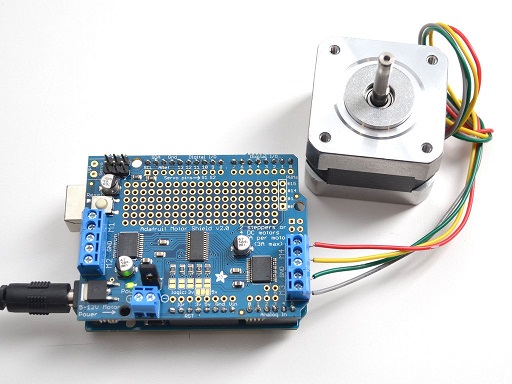
Motor Assembly
Tools - Motor Assembly
#1Phillips Screw Driver
Materials - Motor Assembly
- (1) MA-01: Adafruit Stepper motor - NEMA-17 size - 200 steps/rev, 12V 350mA
- (4) MA-02: M3 Screws
- (1) MA-03: Tone Ring Adapter
Safety Issues - Motor Assembly
- Take general safety precautions when using hand tools
Product - Motor Assembly
(1) TS-01: Holoseat Test Stand Body with TS-08: Motor Assembly attached
Procedure - Motor Assembly
- ...