Assembly Instructions
- Assembly Instructions
Introduction
TBD
Test Stand Body Assembly
Tools - Test Stand Body
- Mitre Saw (preferably powered)
- Pencil
- Carpentry square
- Tape Measure
- Screw Gun
- 1/16" Drill bit (for TS-07: 1-1/4" Fine Thread Drywall Screws)
- 1/8" Drill bit (for TSB-03:
#9x 2-1/2" Coarse Thread Drywall Screws) - Phillips screw driving bit
- (2) 12" (or larger) Bar clamps
- Sand paper
- Paint brush
- Painter's Tape
- Rags
Materials - Test Stand Body
- (2) TSB-01: Side Boards
- (2) TSB-02: Top Boards
- (6) TSB-03:
#9x 2-1/2" Coarse Thread Drywall Screws - (1) TSB-04: 36" Long 2x3 Board
- (1) TS-06: Nema 17 Stepper Motor Mount
- (4) TS-07: 1-1/4" Fine Thread Drywall Screws
- TSB-05: Semi-gloss latex paint
Safety Issues - Test Stand Body
- Always wear safety glasses when working with carpentry tools
- Take care when using saws (especially power saws)
Product - Test Stand Body
(1) TS-01: Holoseat Test Stand Body
Procedure - Test Stand Body
- Produce Side and Top Boards
- Use a miter saw to cut (2) 12" long boards from TSB-04: 36" Long 2x3 Board to produce (2) TSB-01: Side Boards
(also requires tape measure, carpentry square, and pencil) - Use a miter saw to cut (2) 5" long boards from TSB-04: 36" Long 2x3 Board to produce (2) TSB-02: Top Boards
(also requires tape measure, carpentry square, and pencil)
- Use a miter saw to cut (2) 12" long boards from TSB-04: 36" Long 2x3 Board to produce (2) TSB-01: Side Boards
- Assemble the TS-01: Holoseat Test Stand Body
- Use the bar clamps to secure (1) TSB-01: Side Boards and (1) TSB-02: Top Boards in a butt joint flush with the edge of the side board and with their ends aligned
- Drill (2) 1/8" pilot holes through the face of the side board and into the edge of the top board
- Use (2) TSB-03:
#9x 2-1/2" Coarse Thread Drywall Screws to secure the side board to the top board - Repeat the past 3 steps to attach the other TSB-02: Top Boards to the side board making sure the gap between the top boards is wide enough for the TS-06: Nema 17 Stepper Motor Mount
INSERT PIC HERE - Place the TS-06: Nema 17 Stepper Motor Mount against the face of the side board between the top boards
- Drill (4) 1/16" pilot holes into the face of the side board
- Use (4) TS-07: 1-1/4" Fine Thread Drywall Screws to attach the motor mount to the side board making sure its top is flush with the top face of the top boards
INSERT PIC HERE - Use the bar clamps to secure the other TSB-01: Side Boards to the opposite side of the (2) TSB-02: Top Boards
- Drill (2) 1/8" pilot holes through the face of the side board and into the edges of the top boards (1 hole in each top board)
- Use (2) TSB-03:
#9x 2-1/2" Coarse Thread Drywall Screws to secure the side board to the top boards
INSERT PIC HERE
- Paint the Test Stand Body
- Lightly sand the new test stand body
- Wipe down the test stand body with a rag
- Use Painter's Tape to mask the TS-06: Nema 17 Stepper Motor Mount so it does not get paint on it during the next step
- Apply (2) coats of TSB-05: Semi-gloss latex paint to the faces of the test stand body per the paint's instructions
INSERT PIC HERE
Motor Assembly
Tools - Motor Assembly
#1Phillips Screw Driver- Small files
- Blue painter's tape
Materials - Motor Assembly
- (1) MA-01: Adafruit Stepper motor - NEMA-17 size - 200 steps/rev, 12V 350mA
- (4) MA-02: M3 Screws
- (1) MA-03: Tone Ring Adapter
Safety Issues - Motor Assembly
- Take general safety precautions when using hand tools
Product - Motor Assembly
(1) TS-01: Holoseat Test Stand Body with TS-08: Motor Assembly attached
Procedure - Motor Assembly
- Place the TS-01: Holoseat Test Stand Body on its side to provide access to the underside of the TS-06: Nema 17 Stepper Motor Mount
- Place the MA-01: Adafruit Stepper motor into the slot in the motor mount with the wires from the stepper motor facing the gap between the motor mount and the test stand body
- Use the (4) MA-02: M3 Screws to attach the stepper motor to the motor mount
- Pull the wires from the stepper motor through the gap between the motor mount and the test stand body
- Place the TS-01: Holoseat Test Stand Body right side up
- Slide the MA-03: Tone Ring Adapter onto the stepper motor shaft, adjusting fit to the motor shaft and to tone rings as necessary using file/painter's tape
INSERT PIC
Tone Ring Controller
Tools - Tone Ring Controller
- Soldering Iron and stand
- Helping hands, etc
- Small punch
- Small flat screwdriver
#1Phillips screwdriver
Materials - Tone Ring Controller
- (1) TS-01: Holoseat Test Stand Body
- (1) TRC-01: Arduino Uno
- (1) TRC-02: Adafruit Motor/Stepper/Servo Shield for Arduino v2.3 Kit (includes pins and jumper)
- (1) TS-02: Controller Mount (Arduino Bumper)
- (4) TS-15: Small Wood Screws (TBD)
- (1) TS-16: Power adapter (TBD)
- Solder
Safety Issues - Tone Ring Controller
- Care must be taken when using sharp hand tools to avoid cuts
- Care must be taken when using the soldering iron, the tip is very hot
- Always wear safety glasses while working with soldering irons
- Avoid breathing in the soldering fumes, use a vent or hood if needed to provide adequate ventilation
Product - Tone Ring Controller
(1) Holoseat Test Stand with support for Tone Ring Control
Procedure - Tone Ring Controller
- Solder the pins onto the motor shield from the TRC-02: Adafruit Motor/Stepper/Servo Shield for Arduino v2.3 Kit (see Installing Plain Headers for complete details) using the soldering iron, helping hands, and Arduino Uno
- Remove the shield from the Arduino
- Place the TRC-01: Arduino Uno in the TS-02: Controller Mount
- Place the Arduino/Mount sub-assembly on the TS-01: Holoseat Test Stand Body at one end of the top
INSERT PIC - Mark locations for pilot holes using the small punch (deep enough to start the screws into)
- Attach the Arduino/Mount sub-assembly with the (4) TS-15: Small Wood Screws (TBD)
- Attach the motor shield onto the Arduino, ensuring it is firmly seated
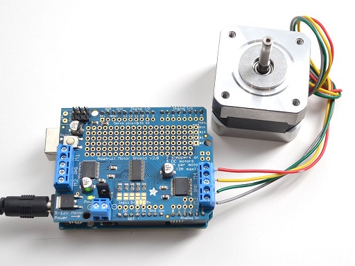
- Attach the jumper to to VIN pins as shown below
- Wire the MA-01: Adafruit Stepper motor to the motor shield as shown in Using Stepper Motors
- Attach the TS-16: Power adapter (TBD) to the barrel jack of the Arduino Uno
| Stepper Motor Wiring, credit Adafruit |
INSERT PIC
Sensor Controller Shield
Tools - Sensor Controller Shield
- Soldering Iron and stand
- Helping hands, etc
- Diagonal cutters
- Needle nose pliers
Materials - Sensor Controller Shield
- (1) SCS-01: Prototype Shield DIY KIT
- (1) SCS-02: TRSS Jack
- (4) SCS-03: Pins
- (2) SCS-04: 750 Ohm Resistor
- (1) SCS-05: LED
- (1) SCS-06: 220 Ohm Resistor
- Hookup wire
- Solder
Safety Issues - Sensor Controller Shield
- Care must be taken when using sharp hand tools to avoid cuts
- Care must be taken when using the soldering iron, the tip is very hot
- Always wear safety glasses while working with soldering irons
- Avoid breathing in the soldering fumes, use a vent or hood if needed to provide adequate ventilation
Product - Sensor Controller Shield
(1) SC-02: Sensor Controller Shield
Procedure - Sensor Controller Shield
- Solder the (4) SCS-03: Pins onto the SCS-02: TRSS Jack
- Solder the underside components onto the SCS-01: Prototype Shield DIY KIT
- Solder green hookup wire from pins 2 and 3 to their target locations according to the PCB diagram
- Solder the SCS-04: 750 Ohm Resistor to their positions according to the PCB diagram
- Solder black hookup wire to its position for the TRSS jack according to the PCB diagram
- Solder red hookup wire to its position for the TRSS jack according to the PCB diagram
INSERT PIC
- Solder the top side components onto the SCS-01: Prototype Shield DIY KIT
- Solder the TRSS Jack and pins sub-assembly to its position according to the PCB diagram
- Solder the SCS-05: LED to its position according to the PCB diagram
- Solder the SCS-06: 220 Ohm Resistor to its position according to the PCB diagram
- Solder red hookup wire to its position from the LED to pin 13 according to the PCB diagram
INSERT PIC
Sensor Controller
Tools - Sensor Controller
- Small punch
#1Phillips screwdriver
Materials - Sensor Controller
- (1) TS-01: Holoseat Test Stand Body
- (1) SC-01: Arduino Uno
- (1) SC-02: Sensor Controller Shield
- (1) TS-02: Controller Mount (Arduino Bumper)
- (4) TS-15: Small Wood Screws (TBD)
Safety Issues - Sensor Controller
- Take general care when working with carpentry tools
Product - Sensor Controller
(1) Holoseat Test Stand with support for Tone Ring and Sensor Control
Procedure - Sensor Controller
- Place the SC-01: Arduino Uno in the TS-02: Controller Mount
- Place the Arduino/Mount sub-assembly on the TS-01: Holoseat Test Stand Body next to the TS-04: Tone Ring Controller making sure to offset the placement so the TS-13: TRSS Cable will fit into the jack on the sensor controller when it is completed
- Mark locations for pilot holes using the small punch (deep enough to start the screws into)
- Attach the Arduino/Mount sub-assembly with the (4) TS-15: Small Wood Screws (TBD)
- Attach the TS-13: TRSS Cable into the TRSS jack on the SC-02: Sensor Controller Shield
- Attach the SC-02: Sensor Controller Shield onto the Arduino, ensuring it is firmly seated
INSERT PIC
Final Assembly
Tools - Final Assembly
- Rubbing alcohol
- Cotton balls
Materials - Final Assembly
- Test Stand
- (1) TS-09: Sensor Mount
- (1) TS-10: Adhesive Tape Square
- (1) TS-11: USB Hub
- (2) TS-12: USB Cables
- (1) TS-14: Holoseat Controller Mount
- (1) TS-16: Power adapter
- (8) TS-19: Command Strip Medium Picture Hanging Strips
Safety Issues - Final Assembly
- None
Product - Final Assembly
Completed Test Stand
Procedure - Final Assembly
- Use (1) TS-12: USB Cable to connect the tone ring controller to the TS-11: USB Hub
- Plug the TS-16: Power adapter into the barrel connector of the tone ring controller
- Use (1) TS-12: USB Cable to connect the sensor controller to the TS-11: USB Hub
- Use rubbing alcohol, cotton balls, and the (8) TS-19: Command Strip Medium Picture Hanging Strips to attach the TS-14: Holoseat Controller Mount to the opposite end of the test stand body from the controllers per the command strip instructions
- Use the TS-10: Adhesive Tape Square to attach the TS-09: Sensor Mount adjacent to the position of the tone ring (when attached)
INSERT PIC