« Previous -
Version 4/8
(diff) -
Next » -
Current version
Aaron Harper, 02/02/2013 10:26 pm
EPS Preliminary Design
Introduction
This design document is broken down in to multiple sections: the Preliminary Design Criteria Review, the Preliminary Schematic, the Preliminary Bill of Materials, and finally the Preliminary Budget. Each of these sections has information which is preliminary in nature, yet attempts have been made to make these as accurate as possible.
Preliminary Design Criteria Review
- EPSRR 1.1 The EPS board uses a Texas Instruments MSP430 microcontroller to measure and store the sensor data
- EPSRR 1.2 the EPS board is made from components which are rated beyond the specification as listed, and the system will operate without direct intervention by an operator.
- EPSRR 2.1 The EPS board is designed in such a way that it may be installed by any person with solar power or electrical wiring experience.
- EPSRR 2.2 The EPS board will have screw holes to mount the board using #10 screws. Alternatively, a DIN rail clip may be used.
- EPSRR 2.3 The EPS board can draw it's power from either monitored load or from another 6-30VDC source.
- EPSRR 3.1 The EPS board shall measure predefined parameters.
- EPSRR 3.1.1 The EPS board measures the ambient temperature in the enclosure using a sensor on the board.
- EPSRR 3.1.2 The EPS board measures voltages of two separate circuits directly with a chip that has built in isolation.
- EPSRR 3.1.3 The EPS board limits the input voltage to the sensor to safe levels using a zener and current limiter.
- EPSRR 3.1.4 The EPS board measures the current of two separate circuits using a directly with a chip that has built in isolation.
- EPSRR 3.2 The EPS board transmits measurement data or fault conditions to the server using a MAC chip with full TCP/IP stack.
- EPSRR 3.2.1 The EPS board will transmit measurement data on demand (web page request).
- EPSRR 3.2.2 The EPS board will be capable of transmitting measurement data on a schedule (FTP or email).
- EPSRR 4.1 The EPS board consumes minimal power. Design maximum is 24mW.
- EPSRR 4.2 See EPSRR 2.3.
- EPSRR 4.3 The EPS board meets all criteria in this area, having a tolerance for massive overvoltage and 12 bit accuracy.
- EPSRR 4.4 The EPS board measures temperature within from -20 to 85C with 12 bit accuracy.
- EPSRR 4.5 The EPS board meets all criteria in this area, having a tolerance for massive overcurrent and 12 bit accuracy.
- EPSRR 4.6 The EPS board meets all criteria in this area, having a MAC controller IC with a fully functional TCP/IP stack and Ethernet Jack with Magnetics.
- EPSRR 6.1 The EPS board is read using standard web protocols which are standardized across all platforms.
- EPSRR 6.2 The EPS board uses standardized connections including Screw terminals and Ethernet.
- EPSRR 8.1 The EPS board is optimized for ease of production.
- EPSRR 8.2 See ESPRR 8.1.
- EPSRR 9.2 The production units appear to cost around $60.00 in parts.
- EPSRR 11.4 Attention has been paid into the durability of the design to keep waste to an absolute minimum.
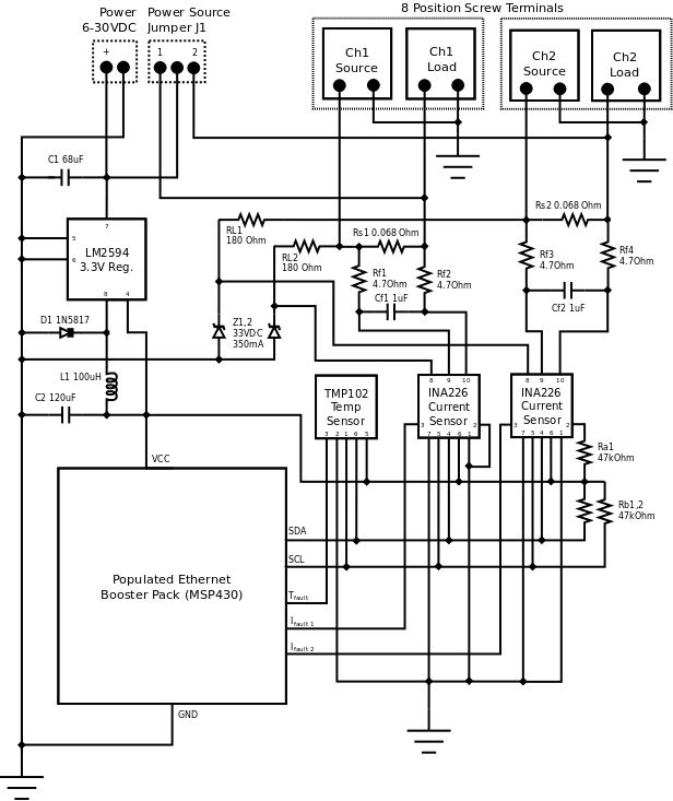
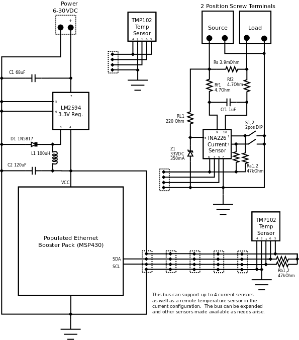
Preliminary Schematic
Preliminary Bill Of Materials
| Schematic | Description | Package |
|---|---|---|
| C1 | 68uF Capacitor | SMD |
| C2 | 120uF Capacitor | Axial |
| Cf1 | 1uF capacitor | SMD |
| Cf2 | 1uF capacitor | SMD |
| D1 | 1N5817 Schottky diode | SMD |
| L1 | 100uH Inductor | SMD |
| Ra1 | 47k Ohm .25W Resistor | SMD |
| Rb1 | 47k Ohm .25W Resistor | SMD |
| Rb2 | 47k Ohm .25W Resistor | SMD |
| Rf1 | 4.7 Ohm .25W resistor | SMD |
| Rf2 | 4.7 Ohm .25W resistor | SMD |
| Rf3 | 4.7 Ohm .25W resistor | SMD |
| Rf4 | 4.7 Ohm .25W resistor | SMD |
| RL1 | 180 Ohm .5W resistor | SMD |
| RL2 | 180 Ohm .5W resistor | SMD |
| Rs1 | 068 Ohm 10W resistor | Axial |
| Rs2 | 068 Ohm 10W resistor | Axial |
| U1 | LM2594M-3.3/NOPB Voltage regulator | SSOP-8 |
| U2 | TMP102 Temp sensor (I2C) | SSOP-6 |
| U3 | INA226 Current and voltage sensor | SSOP-10 |
| U4 | INA226 Current and voltage sensor | SSOP-10 |
| 3 position jumper block | Std | |
| 5mm barrel jack, 2.1mm center pole | Std | |
| 8 position screw terminals | Std | |
| Populated Ethernet Booster Pack (MSP430 MCU) | Board | |
| EPS PC board | Board |
Preliminary Budget
| Schematic | Description | Prototype Cost | Production Cost |
|---|---|---|---|
| C1 | 68uF Capacitor | $.49 | $1.15 |
| C2 | 120uF Capacitor | $0.62 | $0.62 |
| Cf1 | 1uF capacitor | $0.14 | $1.15 |
| Cf2 | 1uF capacitor | $0.14 | $1.15 |
| D1 | 1N5817 Schottky diode | $0.27 | $0.19 |
| L1 | 100uH Inductor | $0.18 | $0.09 |
| Ra1 | 47k Ohm .25W Resistor | $0.37 | $0.03 |
| Rb1 | 47k Ohm .25W Resistor | $0.37 | $0.03 |
| Rb2 | 47k Ohm .25W Resistor | $0.37 | $0.03 |
| Rf1 | 4.7 Ohm .25W resistor | $0.37 | $0.03 |
| Rf2 | 4.7 Ohm .25W resistor | $0.37 | $0.03 |
| Rf3 | 4.7 Ohm .25W resistor | $0.37 | $0.03 |
| Rf4 | 4.7 Ohm .25W resistor | $0.37 | $0.03 |
| RL1 | 180 Ohm .5W resistor | $0.37 | $0.03 |
| RL2 | 180 Ohm .5W resistor | $0.37 | $0.03 |
| Rs1 | 068 Ohm 10W resistor | $2.14 | $2.14 |
| Rs2 | 068 Ohm 10W resistor | $2.14 | $2.14 |
| U1 | LM2594M-3.3/NOPB Voltage regulator | $2.70 | $2.70 |
| U2 | TMP102 Temp sensor (I2C) | $5.95 | $1.69 |
| U3 | INA226 Current and voltage sensor | $6.33 | $3.38 |
| U4 | INA226 Current and voltage sensor | $6.33 | $3.38 |
| 3 position jumper block | $.22 | $.13 | |
| 5mm barrel jack, 2.1mm center pole | $4.95 | $1.12 | |
| 8 position screw terminals | $2.45 | $2.45 | |
| Populated Ethernet Booster Pack (MSP430 MCU) | $25.00 | $25.00 | |
| EPS PC board (qty 10) | $0.00 | $12.00 | |
| Subtotal | $58.21 | $60.75 | |
| Labor | $1362.50 | $135.52 | |
| TOTAL | $1420.71 | $196.27 |