Forums » Block Diagram »
Initial block diagram
Added by Aaron Harper about 13 years ago
An initial block diagram is in development and will be posted here before Wednesday. For now, I will outline this version of the ground station, highlighting the difference between this version and those in the 1.x family, as well as what makes this project unique among ground stations. This version of the ground station will use the user's ham radio(s) for communication rather than include a software defined receiver (SDR) as versions 1.0 and 1.1 have. The reason for this decision is that we do not expect to provide the computer for use, as doing so would blow any attempt at a budget. I am using two radios, a Feidaxin FDC-150 VHF transceiver, and a Baofeng UV-5R dual band (vhf/uhf) transceiver. I may go back to the SDR for receive, but with the current setup, I see no reason to do so until we start to mess around in the L-band (microwave).
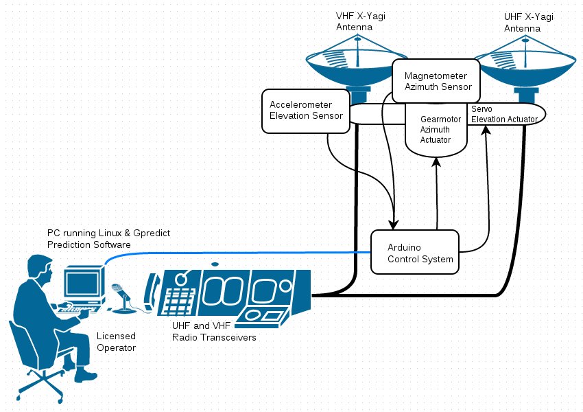
What this means is that since the user will be providing the computer for prediction as well as the radio transceiver(s), the ground station project itself is physically comprised of an azimuth elevation mount and two X-yagi circularly polarized antennas, one for VHF and one for UHF. The software will be Gpredict and hamlib installed on a Panasonic CF-50 laptop running Linux. Gpredict will find the satellite and pass the azimuth and elevation information to Hamlib, the ham radio interface library. Hamlib will talk to the Az-El mount's microcontroller (an arduino) and handshake as though it were an expensive commercial mount such as a Yaesu. This is a vastly simplified approach on a systemic level than even the original ground station concept.
Using a 3 rpm gear motor to rotate a 24" aluminum beam, azimuth is fairly straightforward. To take the load, the beam will sit on a ball bearing turntable rated for several hundred pounds. While not a very strong solution, the amount of mass at 12" from the shaft is trivial. What is unique is the method used to determine azimuth position. Rather than calibrate the mount's direction to true north and add complexity and drag to the mount by adding some sort of positional transducer, this design uses a digital compass module to determine the magnetic heading of the array. The true azimuth will be determined by a set offset (magvar). Future revisions of this design will contain a GPS module and mathematically extract magvar from the GPS position so that the ground station may be used anywhere in the world without calibration.
Elevation for each antenna is accomplished using a ordinary hobby servo. What isn't ordinary is that the servo is mounted in the aluminum channel using an aluminum mount for the servo as well as a pillow block (bearing) to support the weight and torsional loads of the antenna. In keeping with the no calibration design of the azimuth axis, the elevation axis receives positional feedback from an accelerometer. This device will determine zenith from the vector of the gravitational pull, and determine elevation from there. The accuracy of the selected sensors is higher than the selectivity of the antenna's pattern, so while the sensors may give noisy data, this can be sanity checked and mathematically smoothed to yield a stream of good data in a noisy environment.
Additional programming will be in place to prevent sudden motion of the array. Rather than simply turn the motor on in order to rotate the azimuth axis which could impact the longevity of the transmission, the controller will ramp the speed up according to a programmed rate of acceleration (soft start) and slow it down based upon a mathematical process called PID. PID stands for proportional-integral-derivative, which simply means that the speed at which the motion occurs is proportional to the distance it must travel to hit the set point. As it approaches the set point, the motion slows reducing wear on the components and enhancing accuracy. These systems should make the mount have a long productive life chasing satellites.
While all this fancy programming helps the ground station work well for satellite operation, these capabilities will enhance the project's utility to other types of users such as FPV (first person view) aircraft (drone) pilots, high altitude balloon crews, and emergency communications for first responders, disaster response, and government (military) applications. All of these are possible with minor adjustments to the mechanism. Even full mobile use (mounted to a moving vehicle) is possible, thanks to the use of sensors which constantly report real time azimuth and elevation data.
Replies (3)
RE: Initial block diagram - Added by Aaron Harper about 13 years ago
My professor Dr. David Syndergaard posted a reply online that was too thought provoking not to share here:
"Excellent -- thanks for that information.
"Regarding your last paragraph, I assume this set-up will track a spacecraft in low LEO orbit (e.g., the ISS); will the equipment (as is) track fast enough to follow something like a RPA [remotely piloted aircraft]?"
RE: Initial block diagram - Added by Aaron Harper about 13 years ago
In responding, I found some good information and performed some slew rate and torque calculations:
There is a tradeoff. For LEO spacecraft reception like AO-51 or ISS you need two feeds, either a dual band antenna with a duplexer or two antennas with a beam to maintain separation, which is my design. Either will result in enough mass at the end of the rotating shaft that a step down transmission is required. Just like a car where you need more torque, the gear ratio must be changed to provide the required torque at the expense of speed. The 3 RPM gearmotor provides 1102 oz-in of torque which comes to about 5.75 ft-lbs at the ends of the two arms where the elevation servos and yagi antennas are. This is more than sufficient since LEO satellites pass overhead at a rate of 0.33 degrees per second, while the mount has a slew rate of 18 degrees per second. The servos used for the elevation axis have a slew rate of around 90 degrees per second, so there will never be an issue there.
This means that if the antenna is facing the wrong direction (90 degrees out... at 180 the elevation axis just flips the antennas over), we can acquire the bird in 5 seconds, closer to 8 if we consider the acceleration and deceleration (PID) profiles. If we assume the prediction software will begin slewing the antenna as soon as the bird pops above the visual horizon, and it is going to make a pass directly overhead (highest angular velocity), we will be locked on the bird's position by the time it reaches 2.7 degrees above the horizon, which is usually well before the radio can pick it up due to atmospheric attenuation, particularly at higher frequencies. This article has excellent material on LEO tracking: http://www.microwavejournal.com/articles/2937-selecting-a-pedestal-for-tracking-leo-satellites-at-ka-band.
By way of contrast, a FPV aircraft, Drone, or RPA have variable altitudes, velocities, and ranges, so the math is not quite so cut and dry. One thing is pretty clear: turning 180 degrees in 10 seconds at a max speed (no buffer curves) for a fast close RPA pass will not work. That said, the radio links to RPAs tend to be simpler and on a single band. Most FPV aircraft operate on the 2.4 GHz ISM band, so not only are the antennas lighter and smaller, they can be a lower gain and there is only one of them so there is no beam and the mass is closer to the azimuth rotation shaft. All of these make it possible to use a gearmotor with much lower torque, but faster rotation.
If we consider the mass reduction of two servos and antennas at one foot and the 24" aluminum beam (mathematically two 12" beams), then add a 2.4 GHz patch antenna and servo close to the azimuth rotational axis, the torque necessary to rotate this drops by a factor of 40 or more. The required torque goes down to 25 oz-in, which can be managed by a 168 RPM gear motor of identical make and design (different transmission). This brings the slew rate to 1008 degrees per second. Even if we de-rate this by 50% to accommodate the buffer curve, 504 degrees per second is much faster than the elevation axis, making it the weak link.
The bottom line is that in the design of the azimuth system, the slew rate is determined by the motor gearing, and the motor gearing is determined by the amount of mass and distance from the axis (torque). Any specific need like RPAs should be evaluated, and the ground station designed for it. This is why my design in a modular approach, and the beam and two servo setup for dual antennas could easily be replaced by a single servo mounted in the middle with a single pillow block to support the antenna. Speaking of FPV, RPA, and drones, check out these links, especially the last one:
http://diydrones.com/
http://www.youtube.com/watch?v=KRBwEyIQBSA
http://www.youtube.com/watch?v=TVMq-srTY5I
http://www.youtube.com/watch?v=rpBnurznFio
RE: Initial block diagram - Added by Aaron Harper almost 14 years ago
Block diagram:
GS_Block_Diag.jpg - Ground Station Block Diagram (108.5 kB)
(1-3/3)