« Previous -
Version 35/50
(diff) -
Next » -
Current version
Andrew Starr, 09/11/2012 03:51 am
Guiding principles of this STM design
- Minimise the effects of external vibrations by minimising size and mass
- Minimise the effects of temperature variation by matching material coefficients of expansion as closely as possible
- Minimise the effects of electronic noise by locating the sensitive circuitry as close as possible to the signal source
- Maximise instrument flexibility and ease of use by doing as much of the signal processing and control as possible in the digital domain
Also
- Use open source tools for all development
- Source all specialised materials and components from readily-available online sources
Main building blocks of the STM
High frequency vibration isolator
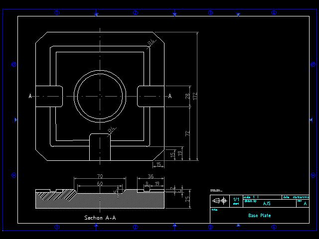
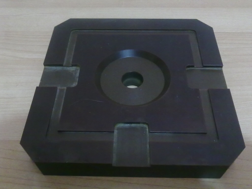
The STM relies on the precise control of the probe-sample gap. Any external vibration has the potential to disrupt this, so efforts must be made to isolate the instrument. Low-frequency vibration isolation is generally done with large pneumatic or elastomer damping systems. I'm hoping to be able to avoid these by making the instrument as compact and stiff as possible, thereby maximising its resonance frequency (and therefore its response to low frequency vibrations). To isolate from high frequencies, I have chosen the 'stacked plate' approach, as described and characterised in "Low- and high-frequency vibration isolation for scanning probe microscopy" (A I Oliva, M Aguilar and Victor Sosa in Measurement Science and Technology, 9 (1998) 383-390)
The drawings for the isolator stack plates can be found here. The plates are each separated with 3 pieces of 5mm long, 5mm diameter pieces of viton rubber as described in the paper. I used an off-the-shelf viton o-ring from a local supplier and cut pieces off, securing with cyanoacrylate glue:
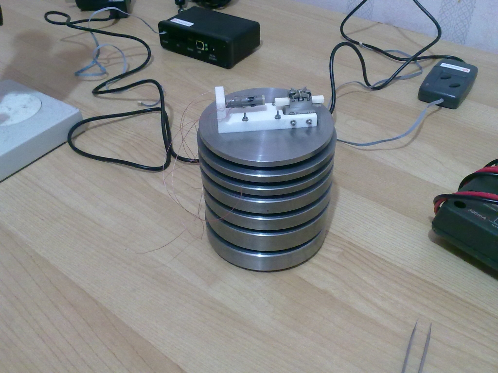
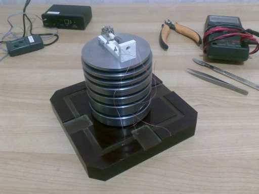
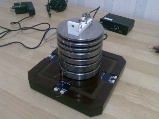
The assembled stack:
I haven't yet characterised the attenuation of the isolator stack - more on this after I've done some testing.
Piezotube
The piezotube was purchased from EBL Products Inc. The material is EBL2 (PZT-5A). The dimensions and electrode configuration are as below:
I've used 36AWG telfon-coated wire (R36A705-00 from Hobby King) to connect to the electrodes, secured with Araldite epoxy glue. The electrical connection is done with Wire Glue conductive adhesive, as I didn't want to risk depolarising the piezotube by heating it with a soldering iron. The Wire Glue joins were reinforced with a coating of cyanoacrylate. It's a bit ugly but the connections are very secure:
Sample mount
Coarse positioner mechanism
Probe holder
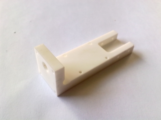
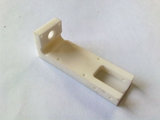
Piezotube and coarse positioner support
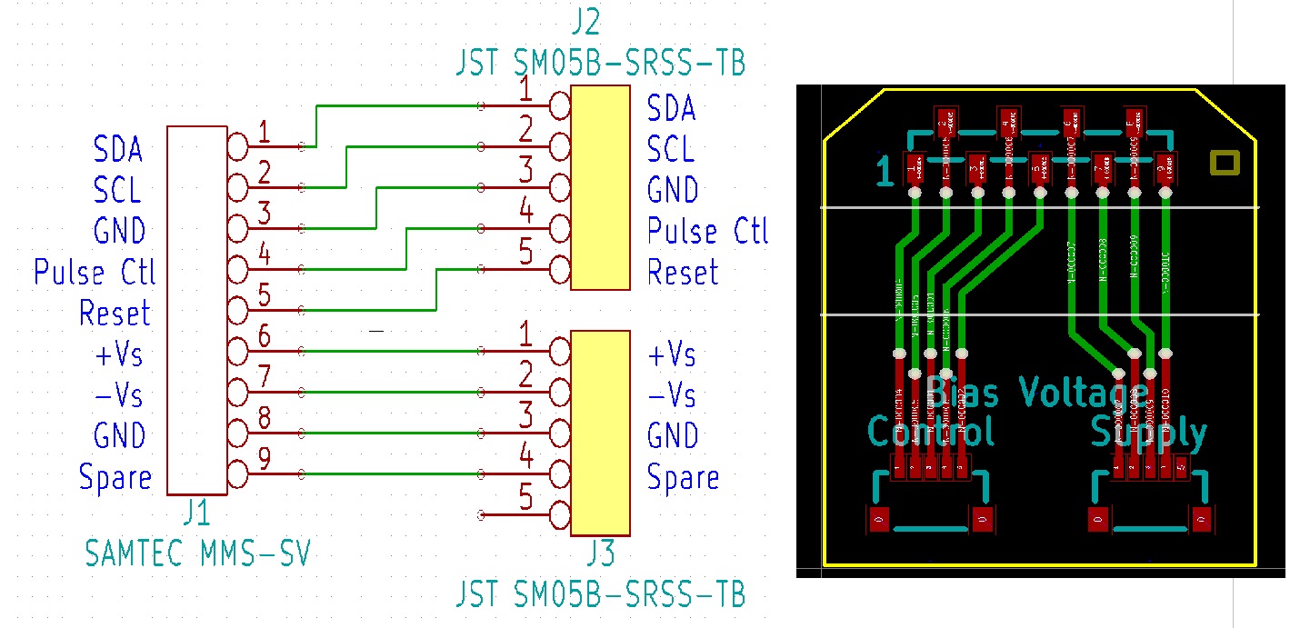
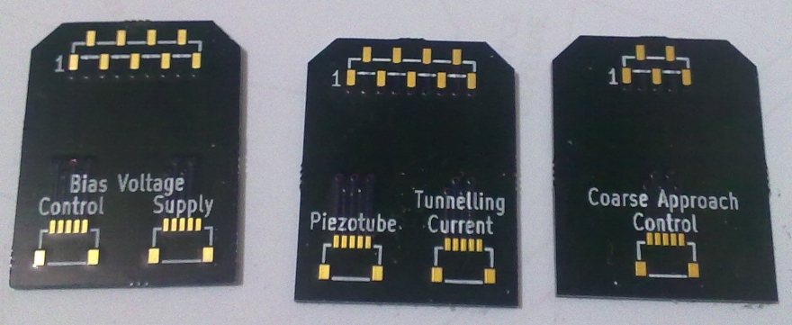
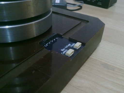
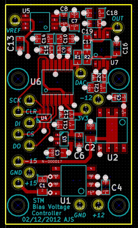
Bias voltage module
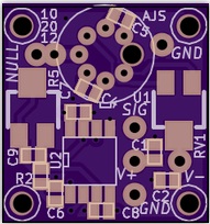
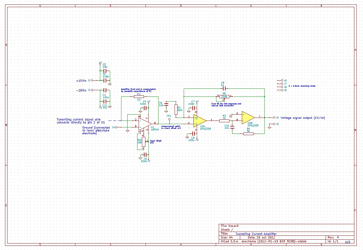
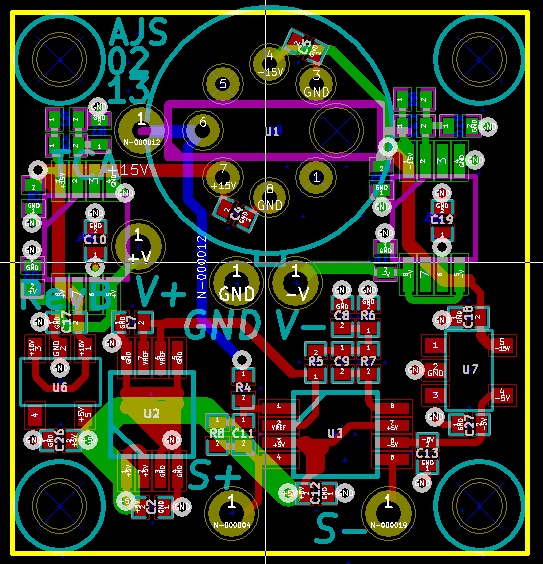
Tunnelling current amplifier
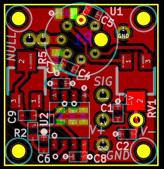
A transimpedance amplifier is required to convert the tunnelling current to a voltage signal. I have opted to go with a high-bandwidth dual stage design as described in A low-noise and wide-band ac boosting current-to-voltage amplifier for scanning tunneling microscopy (Dae-Jeong Kim and Ja-Yong Koo, Review of Scientific Instruments, 76, 023703 (2005)). The design in the original paper uses a OPA111 op-amp as the input amplifier, and a OPA2111 dual op-amp for the ac recovery stage. I have opted to use an AD549 in a TO-99 case, as the TO-99 offers the ability to connect the metal case to ground potential, which should assist in screening out external noise. For the dual op-amp I have opted to use an OPA2209, as it is a much better performing device (lower noise, greater gain bandwidth, greater CMRR etc). The design files (in Kicad format) can be found here.
The amplifier will mount onto the back of the ceramic support, so the signal wire carrying the tunnelling current can be as short as possible.