Guiding principles of this STM design
- Minimise the effects of external vibrations by minimising size and mass
- Minimise the effects of temperature variation by matching material coefficients of expansion as closely as possible
- Minimise the effects of electronic noise by locating the sensitive circuitry as close as possible to the signal source
- Maximise instrument flexibility and ease of use by doing as much of the signal processing and control as possible in the digital domain
Also
- Use open source tools for all development
- Source all specialised materials and components from readily-available online sources
Main building blocks of the STM
High frequency vibration isolator
The STM relies on the precise control of the probe-sample gap. Any external vibration has the potential to disrupt this, so efforts must be made to isolate the instrument. Low-frequency vibration isolation is generally done with large pneumatic or elastomer damping systems. I'm hoping to be able to avoid these by making the instrument as compact and stiff as possible, thereby maximising its resonance frequency (and therefore its response to low frequency vibrations). To isolate from high frequencies, I have chosen the 'stacked plate' approach, as described and characterised in "Low- and high-frequency vibration isolation for scanning probe microscopy" (A I Oliva, M Aguilar and Victor Sosa in Measurement Science and Technology, 9 (1998) 383-390)
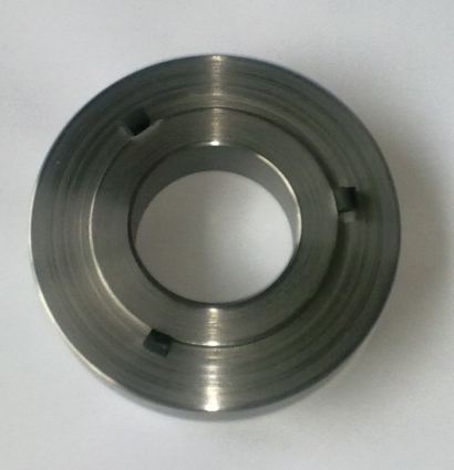
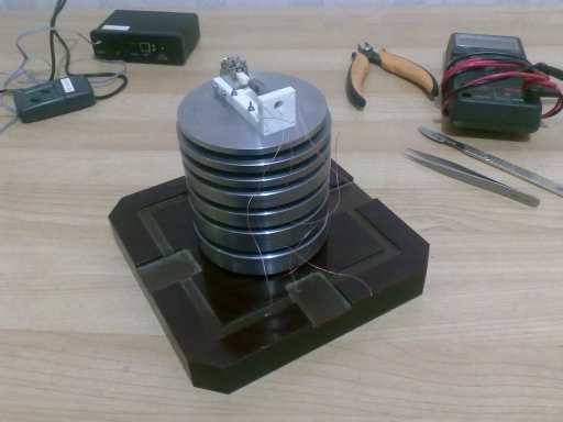
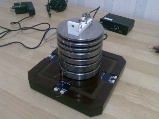
The drawings for the isolator stack plates can be found here. The plates are each separated with 3 pieces of 5mm long, 5mm diameter pieces of viton rubber as described in the paper. I used an off-the-shelf viton o-ring from a local supplier and cut pieces off, securing with cyanoacrylate glue:
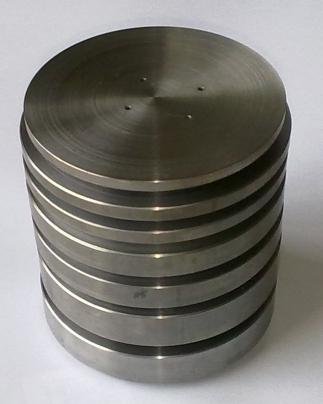
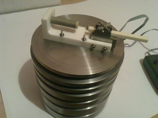
The assembled stack:
I haven't yet characterised the attenuation of the isolator stack - more on this after I've done some testing.
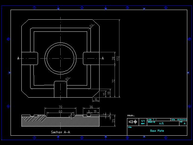
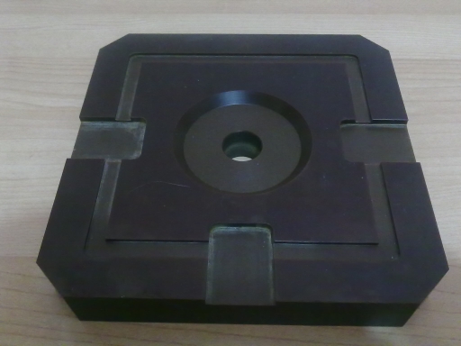
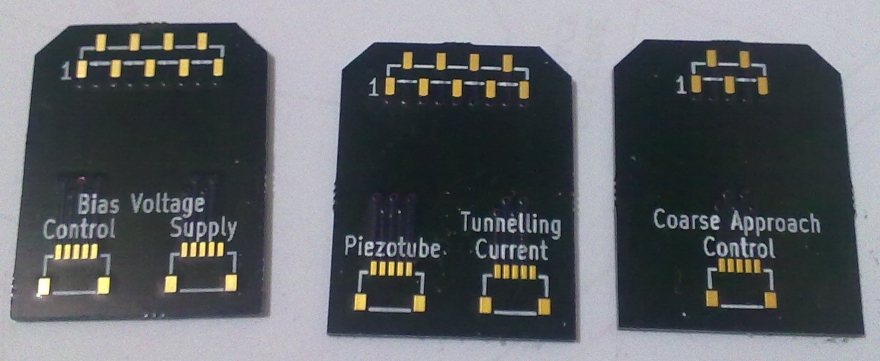
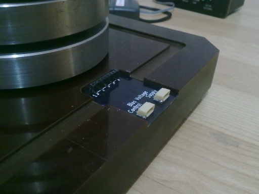
Base plate
The isolator stack will rest on a tufnol base plate, which will provide connection points for the wires coming off the instrument. These connection points will run back to the control module via JST SR-series connectors on adapter PCBs in 3 recesses on the base plate. A shallow rectangular 'trench' in the plate runs around the base of the isolator stack. This is a mating recess for a steel fabric-lined hood that will cut down acoustic and temperature disturbances, and provide a mounting port for a USB microscope (used in the initial coarse approach phase of a measurement).
The drawing file can be found here.
Piezotube
The piezotube was purchased from EBL Products Inc. The material is EBL2 (PZT-5A). The dimensions and electrode configuration are as below:
I've used 36AWG telfon-coated wire (R36A705-00 from Hobby King) to connect to the electrodes, secured with epoxy glue. The electrical connection is done with Wire Glue conductive adhesive, as I didn't want to risk depolarising the piezotube by heating it with a soldering iron. The Wire Glue contacts were reinforced with a coating of cyanoacrylate. It's a bit ugly but the connections are very secure:
Sample mount
Coarse positioner mechanism
The microscope must have a way of bringing the probe to within tunnelling distance (i.e. nanometres) of the sample without the two crashing into each other. This requires a mechanism that possesses the following properties:
- low mechanical vibration
- low mass
- nanometer resolution
Two traditional approaches have been stepper motors and 'inchworm'-type piezoelectric devices. Stepper motors are heavy and require lever-reduction systems to achieve the required linear distance resolution. The inchworm devices typically use exotic materials and can be difficult to control.
I have opted to use a Piezo LEGS linear motor from PiezoMotor. This motor weighs only 23g, has nanometer resolution, and PiezoMotor supplies a control module that enables the motor to be controlled via USB. The drive rod is made from alumina, which means it will have a similar coefficient of thermal expansion to the ceramic holder and piezotube.
Probe holder
Piezotube and coarse positioner support
The piezotube and coarse positioner must be attached to a thermally stable, rigid platform to maintain their relative orientations. The platform must be thermally stable to avoid measurement errors due to thermal expansion and contraction, and it must be rigid to minimise the effects of vibration. I have opted for a simple 'L'-shaped design made from Macor, a machinable ceramic made by Corning Glass. Since the piezotube and coarse positioner rod are made from ceramic and alumina respectively, any expansion or contraction in these components that would alter the distance between the probe and sample will tend to be cancelled out by a similar expansion or contraction in the support platform. M1.6 mounting hardware is used to secure the electronics to the support, and the support to the isolator stack.
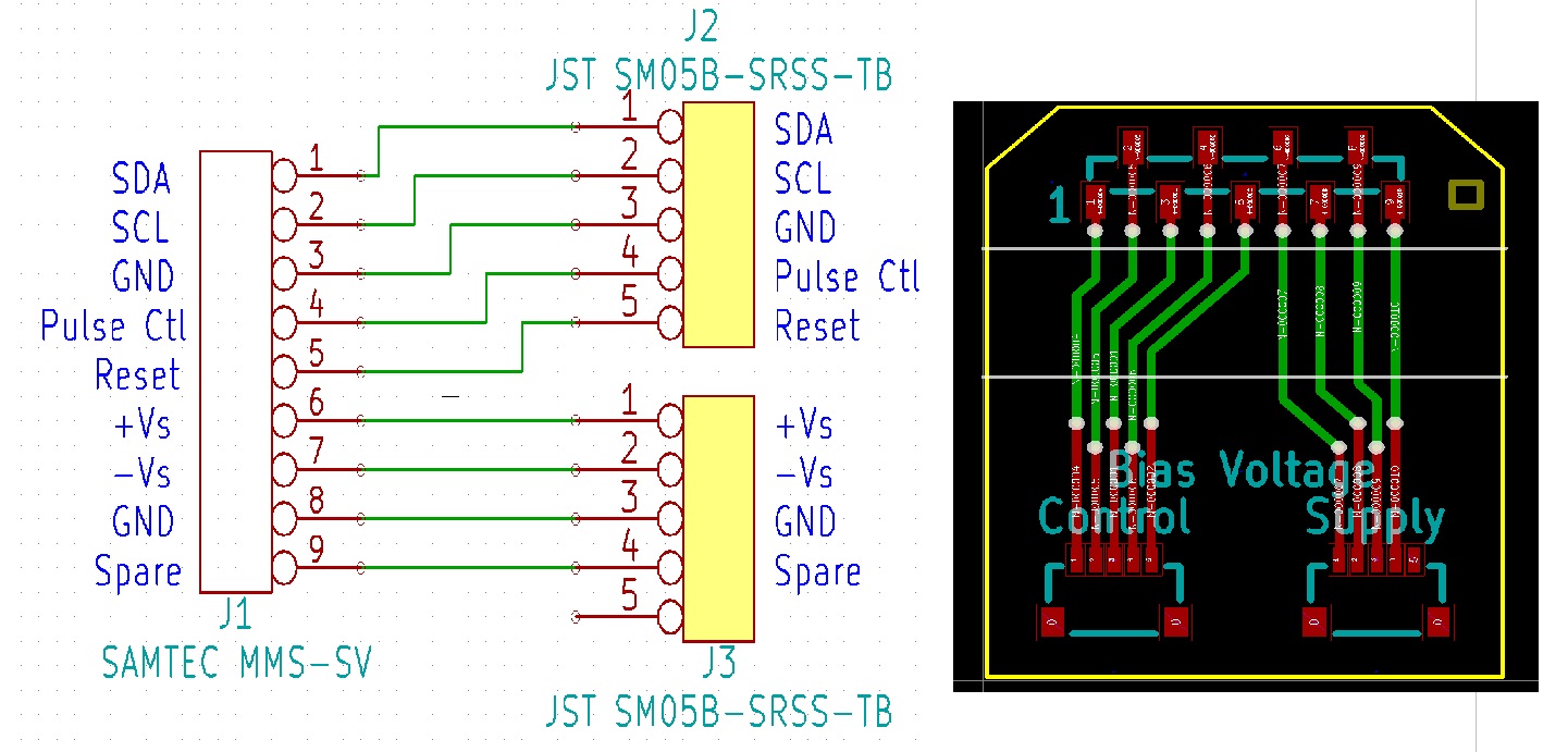
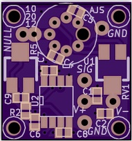
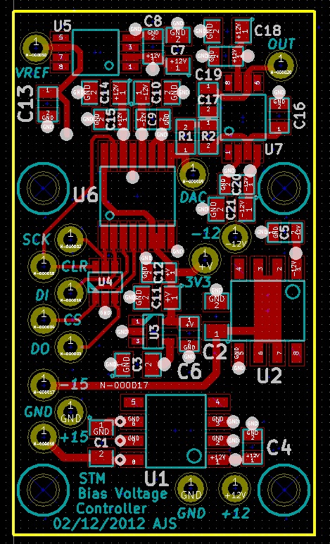
Bias voltage module
This module has 2 functions:
- Provide a low-level bias voltage - typically on the order of 100mV - between the probe tip and sample to generate the tunnelling current
- Generate (relatively) high voltage pulses - typically several volts - to experiment with atomic lithography
I have chosen a 12-bit bipolar DAC that will generate -10 to 10V. 12 bits gives an output resolution of 5mV, which is probably overkill. The DAC output is conditioned with a Sallen-Key filter to reduce noise bandwidth. The filter cutoff frequency is 1 kHz.
The DAC output is controlled via an SPI interface. The board is supplied with +/-15V rails, which are downregulated to +/-12V for the analogue output, and to 3.3V for the digital interface of the DAC.

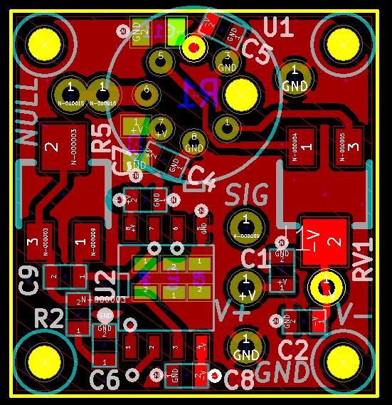
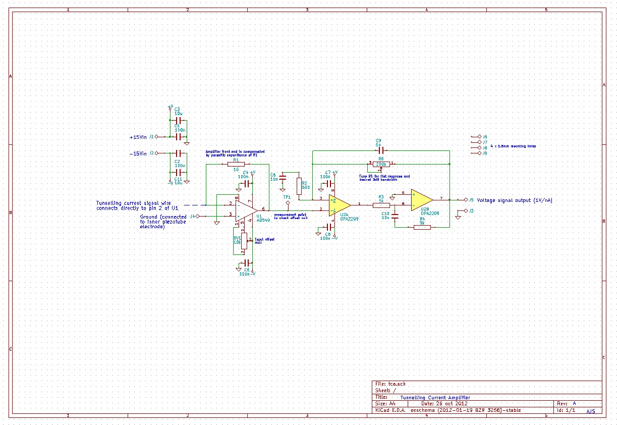
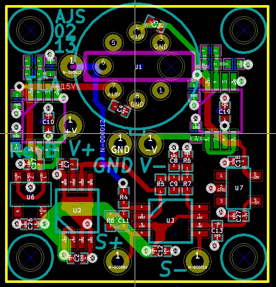
Tunnelling current amplifier
A transimpedance amplifier is required to convert the tunnelling current to a voltage signal. I have opted to go with a high-bandwidth dual stage design as described in A low-noise and wide-band ac boosting current-to-voltage amplifier for scanning tunneling microscopy (Dae-Jeong Kim and Ja-Yong Koo, Review of Scientific Instruments, 76, 023703 (2005)). The design in the original paper uses a OPA111 op-amp as the input amplifier, and a OPA2111 dual op-amp for the ac recovery stage. I have opted to use an AD549 in a TO-99 case, as the TO-99 offers the ability to connect the metal case to ground potential, which should assist in screening out external noise. For the dual op-amp I have opted to use an OPA2209, as it is a much better performing device (lower noise, greater gain bandwidth, greater CMRR etc). The design files (in Kicad format) can be found here.
The amplifier will mount onto the back of the ceramic support, so the signal wire carrying the tunnelling current can be as short as possible.