« Previous -
Version 6/17
(diff) -
Next » -
Current version
Andrew Starr, 10/19/2012 10:57 pm
Lab Journal
20 Oct, 2012 - Tunnelling Current Amplifier simulation
The tunnelling current amplifier is an example of a transimpedance amplifier: it converts a current input into a voltage output. This amplifier is a critical circuit in the microscope, so I have taken advantage of available electronic simulation software to test and tune the design before committing to a PCB.
Bandwidth vs noise
In a transimpedance amplifier there is an unavoidable tradeoff between the bandwidth of the amplifier response and its output noise. The higher the bandwidth of the amplifier, the faster the response, but also the higher the output noise will be. These two parameters have the following effects on the microscope performance:
- Bandwidth affects response time of the amplifier to a change in tunnelling current, and therefore affects the rate at which the sample can be scanned.
- Noise affects the vertical resolution of the tunnelling current, and therefore limits the vertical resolution of the sample data. If the noise is bad enough it may also cause problems in maintaining the tip-sample tunnelling distance.
The design of the tunnelling current amplifier is determined by the following questions:
- What is the highest acceptable level of output noise?
- What is the maximum bandwidth that satisfies the output noise requirement?
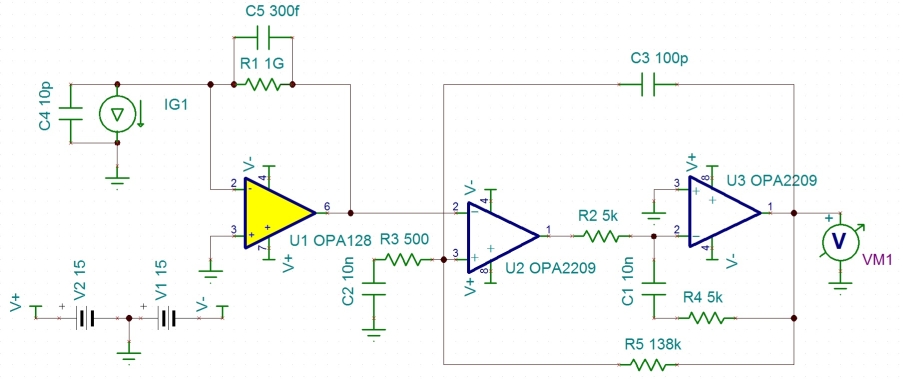
- Does the composite amplifier offer a bandwidth advantage that justifies its greater complexity for this application?
Simple vs composite amplifier
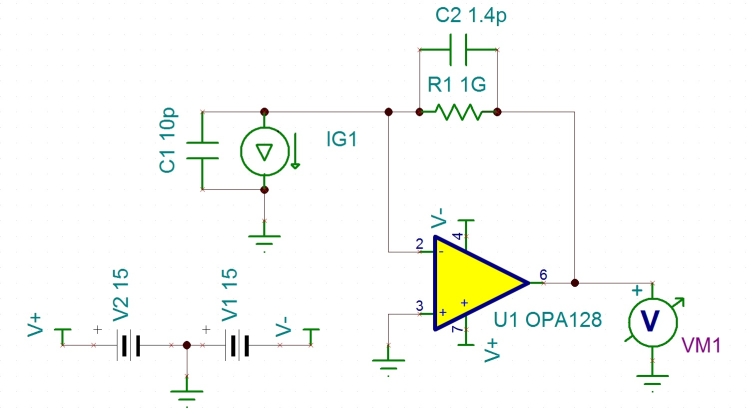
The 'classic' transimpedance amplifier design for small currents such as photodiodes etc is an op-amp with negative feedback via a single large value resistor, with a compensation capacitor to prevent oscillation due to noise gain:
![]()
R1 is the feedback resistor, C2 is the compensation capacitance (including the parasitic capacitance of the resistor itself). C1 represents the parasitic capacitance of the current source IG1. The output of the circuit is nominally is 1V/nA.
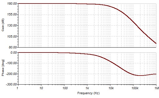
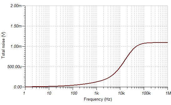
This circuit has the virtue of being very simple, and output noise is comparatively low - mostly coming from thermal noise of R1. However the bandwidth is very poor, typically a few hundred Hertz