« Previous -
Version 12/17
(diff) -
Next » -
Current version
Andrew Starr, 10/20/2012 12:16 am
Lab Journal
20 Oct, 2012 - Tunnelling Current Amplifier simulation
The tunnelling current amplifier is an example of a transimpedance amplifier: it converts a current input into a voltage output. This amplifier is a critical circuit in the microscope, so I have taken advantage of available electronic simulation software (TINA-TI version 9, free to download from Texas Instruments) to test and tune the design before committing to a PCB. I have a choice between a simple, 'classic' transimpedance amplifier and a more complex - but possibly better performing - 'composite' amplifier.
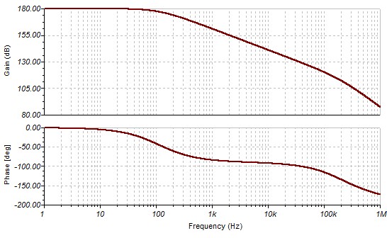
Bandwidth vs noise
In a transimpedance amplifier there is an unavoidable tradeoff between the bandwidth of the amplifier response and its output noise. The higher the bandwidth of the amplifier, the faster the response, but also the higher the output noise will be. These two parameters have the following effects on the microscope performance:
- Bandwidth affects response time of the amplifier to a change in tunnelling current, and therefore affects the rate at which the sample can be scanned.
- Noise affects the vertical resolution of the tunnelling current, and therefore limits the vertical resolution of the sample data. If the noise is bad enough it may also cause problems in maintaining the tip-sample tunnelling distance.
The design of the tunnelling current amplifier is guided by the following questions:
- What is the highest acceptable level of output noise?
- What is the maximum bandwidth from each design that satisfies the output noise requirement?
- Does the composite amplifier offer a bandwidth advantage that justifies its greater complexity for this application?
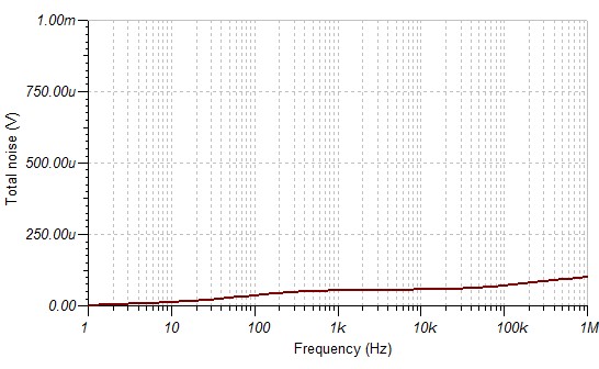
Output noise
Simple vs composite amplifier
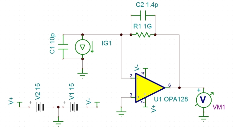
The 'classic' transimpedance amplifier design for small currents such as photodiodes etc is an op-amp with negative feedback via a single large value resistor, with a compensation capacitor to prevent oscillation due to noise gain:
![]()
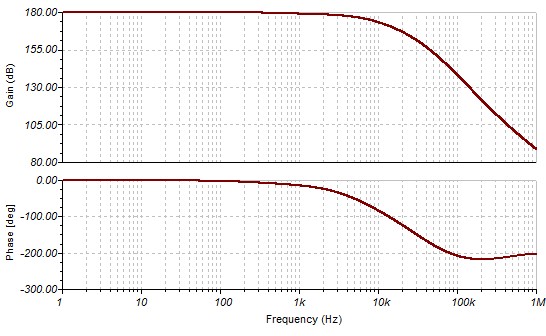
R1 is the feedback resistor, C2 is the compensation capacitance (including the parasitic capacitance of the resistor itself). C1 represents the parasitic capacitance of the current source IG1. The output of the circuit is nominally is 1V/nA.
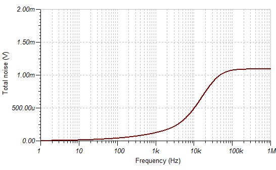
Assuming 10pF capacitance for the tunnelling signal input, and using only the parasitic capacitance of the feedback resistor for compensation (around 0.3pF for a leaded resistor), the 3dB bandwidth is about 520 Hz - not great, but possibly usable. The output noise looks to be around 200uVrms.
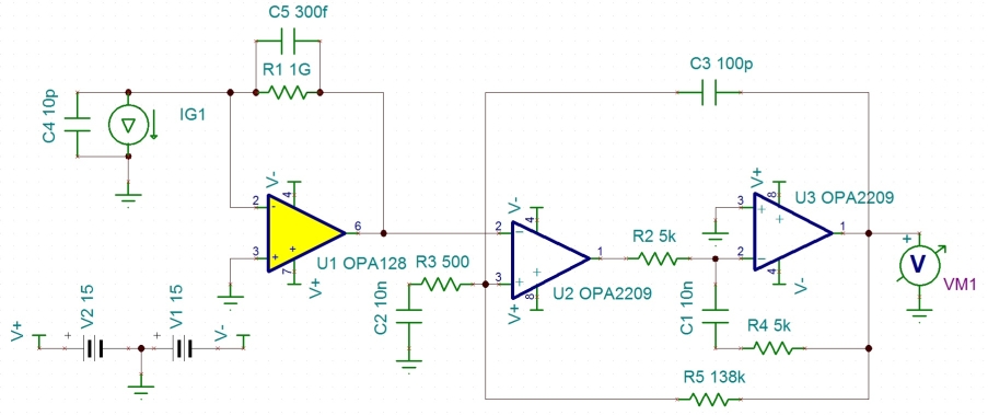
An alternative, 'composite' amplifier is described in A low-noise and wide-band ac boosting current-to-voltage amplifier for scanning tunneling microscopy (Dae-Jeong Kim and Ja-Yong Koo, Review of Scientific Instruments, 76, 023703 (2005)). This amplifier has a 'classic' front end, followed by an 'ac-boosting' section to recover the high-frequency part of the signal:
![]()
This circuit needs careful tuning. C2, C3 and R5 need to be chosen so that the gain response is flat over the desired bandwidth. Increasing C2, decreasing C3, or increasing R5 has the effect of increasing bandwidth.