Index by title
Ground Sphere Prototype Assembly Instructions v0.2
Introduction
Version 0.2 is the second prototype, which sacrifices some of the flexibility of v0.1 in order to move toward a more polished kit version of the ground station. The overall design is the same between v0.1 and v0.2, but the details and several components have changed. Below are the assembly instructions for v0.2.
Structural Component Pre-assembly
Tools
- Hacksaw or chop saw
- Sharp knife
- Drill or drill press
- Ruler or caliper
- Pen or pencil
- Optional: Centering jig for drill press
Materials
- 1ea (ANT01) ¾” sched 40 PVC coupler
- 1 ea length of ¾” PVC sched 40 pipe 3” or longer. Makes (ANT02) coupling sections
- 1ea (ANT05) ¾” PVC sched 40 to ½” NPT male adapter
- 1ea (ANT06) ¾” PVC sched 40 end cap
- PVC cement primer (purple solvent)
- PVC pipe cement
- Optional: PVC safe spray paint in a desirable color.
Safety issues
- Care must be taken when working with powertools, sharp blades, or saws.
- When using a chop saw, drill, or drill press, eye protection should be worn.
- PVC solvent and cement must be used in well ventilated areas.
- Spray paint must be used in a well ventilated area, and should be done in a paint booth or outdoors.
Product or Outcome
All plastic components for the Ground Sphere Mk2 upper structure.
Procedure
- Using a chop saw or hack saw, cut 2 sections of ¾” PVC sched 40 pipe 1¼” long.
- Using a sharp knife debur the inside and outside of the sections.
- These become coupling sections (ANT02).
- Using the PVC cement primer (purple solvent), lightly coat the whole outside of both coupling sections.
- Without dipping the applicator back into the primer, lightly coat the inside of the ¾” PVC sched 40 to ½” NPT male adapter. (ANT05).
- Without dipping the applicator back into the primer, lightly coat the inside of the ¾” PVC sched 40 end cap (ANT06).
- Lightly coat the inside of the unthreaded side of the ¾” PVC sched 40 to ½” NPT male adapter (ANT05) with PVC cement.
- Quickly insert one of the coupling sections (ANT02) and set aside to cure.
- Lightly coat the inside sides of the ¾” PVC sched 40 end cap (ANT06) with PVC cement.
- Quickly insert the remaining coupling section (ANT02) and set aside to cure.
- As accurately as possible drill a 3/16” hole in the exact center of the side on the ¾” sched 40 PVC coupler (ANT01). The use of a drill press and centering jig is recommended.
- Rotating the part 180 degrees, drill a 3/16” hole in the exact center of the opposite side on the ¾” sched 40 PVC coupler (ANT01).
- Rotating the part 90 degrees, drill a 3/16” hole in the exact center of the ¾” sched 40 PVC coupler (ANT01) between the first two holes.
- Rotating the part 180 degrees, drill a 3/16” hole in the exact center of the remaining side on the ¾” sched 40 PVC coupler (ANT01).
- The holes should be at the 12 o’clock, 3 o’clock’ 6 o’clock, and 9 o’clock positions when sighting down the ¾” sched 40 PVC coupler (ANT01).
- If it is desirable to paint the ground station components, this is a good time to do so.
- Set the units aside for integration with the antenna body.
Assembling the Phasing Loop
Tools
- Needle nose pliers
- Wire cutters
- Wire strippers
- X-acto knife
- Terminal crimper
- Ruler or caliper
- Dental pick or needle
Materials
- 3ea (ANT10) Insulated crimp ring terminal Red (22-18 AWG)
- 1ea (ANT11) Insulated crimp ring terminal Blue (16-14 AWG)
- 1ea (ANT13) Antenna line, SMA female connector to pigtail
- 1ea (ANT15) Tuned length of RG62u 90ohm coaxial cable
Safety issues
- Care must be taken when working with hand tools, sharp blades, or sharp points.
- Coaxial cable wires, both the center conductor and shield wire can easily pierce the skin.
- Should a shield wire pierce the skin, remove it carefully since it can break off well below the surface of the skin, requiring painful removal
Product or Outcome
All radio frequency (RF) components for the Ground Sphere Mk2 upper structure.
Procedure
- Cut the RG62u 90ohm cable (ANT15) to precisely 2.775”.
- Note: the RG62u 90ohm cable (ANT15) should already be cut to length.
- Verify the length.
- Using the X-acto knife, strip ¾” from each end of the RG62u segment (ANT15) and retain the insulation tube.
- Note: If something goes wrong with the RG62u segment (ANT15), do not cut off the messed up end and retry. It is a specific length and must remain so.
- In the event of breakage, use another segment of the correct length.
- Using the dental pick or needle, gently unbraid the shield from both ends of the RG62u segment, twisting the strands into a single strand.
- Some breakage of the shield strands is unavoidable.
- Remove any broken strands.
- Using the X-acto knife, strip ¼” of insulation from the center conductor from both ends of the RG62u segment (ANT15).
- With the needle nose pliers, form a hook in the end of both of the center conductors as small as possible, a 1/32” across.
- Slip a red ring terminal (ANT10) over one of the center conductors. The hook should just fit into the hole of the ring terminal (ANT10).
- Crimp the ring terminal (ANT10) with the crimper.
- Trim the insulation tubes removed from the RG62u segment (ANT15) in step 2 into ½”.
- Slip one of the ½” insulation tubes over the shield wires twisted in step 3 on the same side as the terminal we just terminated in step 7.
- Insert a red ring terminal (ANT10) over the exposed twisted shield wire insulated with the insulation tube in step 9.
- Allow a small amount of play in the length (the insulation tube should not be tight)
- Crimp the ring terminal with the crimper
- Cut the antenna line (ANT13) at six inches from the end of the connector and strain relief.
- Use the wire strippers at the 14ga setting and gently strip ¾” from the antenna line ( ANT13) and retain the insulation tube.
- Using the dental pick or needle, gently unbraid the shield from the stripped end of the antenna line (ANT13), twisting them into a single strand.
- Some breakage of the shield strands is unavoidable.
- Remove any broken strands.
- Using the X-acto knife, very carefully strip ¼” of insulation from the exposed center conductor on the antenna line (ANT13).
- Note: If something goes wrong with the antenna line (ANT13), you may cut off the messed up end and retry, beginning at step 11.
- There is enough extra to correct one mistake in this manner.
- In the event of a second mistake on the same antenna line, discard the shortened antenna line and use another beginning at step 10.
- Slide the remaining ½” insulation tube over the remaining shield wires of the RG62u (ANT15) segment twisted in step 3.
- Trim the insulation tube removed from the antenna line (ANT13) to a length of ½”
- Carefully slide the insulation tube over the shield strands of the antenna line (ANT13) twisted together in step 12.
- Insert a blue ring terminal (ANT11) over the exposed twisted shield wires on both the antenna line (ANT13) and the RG62u segment (ANT15) insulated with the insulation tubes in steps 14 and 16.
- Allow a small amount of play in the length (the insulation tube should not be tight)
- Crimp the ring terminal with the crimper
- Insert a red ring terminal (ANT10) over both of the remaining exposed center conductors, on the antenna line (ANT13) and the RG62u segment (ANT15) and crimp the ring terminal tightly.
- Set the unit aside for integration with the ground plane and antenna body
Building the Ground Plane
Tools
- Scissors
- Fine point permanent marker (Sharpie)
- Clothespins
- Wide eyed needle
- Ruler or tape measure
- X-acto knife
- Flush cutters or small diagonal cutters
- A short piece of ¾” Schedule 40 PVC pipe for a fit test.
Materials
- Paper for the pattern
- 1 ea (ANT16) Conductive fabric
- 1 ea (ANT17) Round ABS plastic needlepoint canvas 9” diameter
- 1 ea (ANT18) 15ft length of conductive thread
Safety Issues
- Care must be taken when working with hand tools, sharp blades, or sharp points.
Product or Outcome
The complete ground plane assembly for the Ground Sphere Mk2.
Procedure
- Take a piece of paper and fold it in half four times on the diagonal until you have a cone.
- Using a ruler or tape measure, measure from the folded point and mark the radius at 3¾” on the paper with a fine point permanent marker.
- Using the scissors, cut the edge on a slight convex curve.
- Using a ruler or tape measure, measure from the folded point and mark the radius at ½” on the paper with a fine point permanent marker.
- Cut the radius on a slight concave curve.
- Unfold the paper and lay flat.
- Verify the dimensions of the finished template. It should be a 7 ½ inch diameter circle with a 1 inch diameter inner circle removed.
- This pattern may be reused if multiple ground planes are to be made.
- Using a ruler or tape measure, measure the plastic needlepoint canvas (ANT17) and measure across the center. Use one of the four sections that go straight across as a guide.
- Using a fine point permanent marker, mark the gap between rings that exceeds 3½” from the centerpoint of the plastic needlepoint canvas (ANT17).
- Using a fine point permanent marker, mark the gap between rings that is ½” from the centerpoint of the plastic needlepoint canvas (ANT17).
- Using a fine point permanent marker mark the plastic all the way around the radii of the measurements and marks made in steps 11 and 12, making a 7” and 1” circle.
- Using an X-acto knife, cut out center circle from the plastic needlepoint canvas (ANT17). Leave the teeth of the plastic needlepoint canvas, which will be trimmed later.
- Using scissors, cut out the outer circle and trim the teeth flush from the plastic needlepoint canvas (ANT17).
- Use flush cutters or small diagonal cutters to trim the nubs from inner edge of the center 1” circle on the the plastic needlepoint canvas (ANT17) as tightly as can be accomplished with the tool.
- DO NOT attempt to make the inner radius of the plastic needlepoint canvas (ANT17) completely smooth, as the remaining nubs hold the ground plane assembly snugly in place in the antenna coupling section (ANT02).
- Test fit the plastic needlepoint canvas (ANT17) on a section of ¾” Schedule 40 PVC pipe.
- The plastic needlepoint canvas (ANT17) should fit, but not tightly nor deforming.
- Trim as necessary.
- Fold the paper pattern in half on one of the fold lines from step 1.
- Fold the conductive fabric (ANT16) in half at 4” from the cut edge so that the underside (less shiny side) is visible.
- Place pattern on the folded conductive fabric (ANT16) so that it is completely on the conductive fabric (ANT16) and the fold of the pattern is flush with the fold of the fabric.
- Using a fine point permanent marker trace both the inner and outer radius of the pattern on the folded fabric.
- With the conductive fabric (ANT16) still folded, cut out conductive fabric (ANT16) on the outer circumference tracing lines from step 21.
- Cut out center hole following the inner circumference tracing lines from step 21.
- Test fit the conductive fabric (ANT16) on a section of ¾” Schedule 40 PVC pipe as was done with the plastic needlepoint canvas in step 17.
- Use clothespins to hold conductive fabric (ANT16) and plastic needlepoint canvas (ANT17) together at multiple points. There should be a ¼ inch overlap of conductive fabric (ANT16) on the outside edge. This overlap will shrink as the ground plane is sewn to the plastic needlepoint canvas.
- Thread the wide eye needle with a 3ft section of conductive thread.
- Knot one end
- Position the needle near the unknotted end of the thread.
- Note: stitch the Ground Sphere ground plane assembly with a single strand of conductive thread (ANT18).
- DO NOT use double strands, as this reduces the electrical conductivity and wastes thread.
- Starting from the plastic needlepoint canvas (ANT17) side on the innermost ring, stitch down through a hole in the plastic needlepoint canvas (ANT17), drawing the conductive thread (ANT18) all the way through to the knot.
- Move one square in either direction (clockwise or counterclockwise) and stitch through both layers drawing the conductive thread (ANT18) all the way through.
- Continue in the chosen direction, working around the ring of holes, up one square, down the next. Go all the way around one 'circle' in the plastic needlepoint canvas.
- Note: Maintain a steady tension on the conductive thread while drawing it through the fabric. Once the thread stops, DO NOT tighten the loop further.
- Sew slowly to prevent the conductive thread (ANT18) from knotting.
- The conductive thread (ANT18) tangles more easily than regular and is more likely to break.
- Keep the conductive fabric (ANT16) as smooth as possible.
- Avoid folds or twists in the conductive fabric (ANT16) by going slowly and adjusting the clothespins frequently.
- When the circle is complete, skip a row and start the next circle outward.
- When about 5-6” of conductive thread (ANT18) remain, work the conductive thread (ANT18) through the backs of the stitches on the plastic needlepoint canvas (ANT17) side heading back to the starting point where the knotted tail remains.
- Bring the conductive thread (ANT18) up and through the square at the beginning (where the knot is) and remove the needle from the conductive thread (ANT18) leaving the remainder as a tail. These strands will be used to electrically connect the ground plane assembly to the antenna ground.
- Should it be necessary to start a new thread during a round:
- Knot the two pieces of conductive thread (ANT18) together with a square knot and continue sewing.
- The conductive thread (ANT18) should always be linked to a previous section, unless it ends at the original square in the central circle.
- When 5-6 full circles are done, move to the outer row at the very edge of the plastic needlepoint canvas (ANT17) with a new piece of conductive thread (ANT18), prepared as per step 26.
- Stitch all the way around the outermost holes of the plastic needlepoint canvas (ANT17).
- Once the outer circle is complete, skip a row inward and start the next circle.
- Continue this pattern until there are stitches in every other row from the edge to the center of the plastic needlepoint canvas (ANT17).
- Once the stitching is complete, ensure all conductive thread (ANT18) ends travel down to the center of the plastic needlepoint canvas (ANT17) forming the ground line or are tied on to previous threads which do.
- Trim off the excess conductive fabric (ANT16) from the outer edge of the ground plane.
- Taking care to not cut into the plastic needlepoint canvas(ANT17) below the conductive fabric (ANT16).
- The surplus conductive fabric (ANT16) may be uneven or irregular. This is normal and is due to the pull of the conductive fabric (ANT16) and the tension of the stitches.
- Set the unit aside for integration with the phasing loop and RF line assembly.
Installing the Phasing Loop Ground Plane and RF Line Assembly
Tools
- Needle nose pliers
- Wire cutters
- #2 phillips screwdriver
- Dental pick or needle
- Bench vice or other method of holding the work
- Sharpie or other permanent marker
Materials
- 1 ea (ANT01) ¾” sched 40 PVC coupler with holes drilled at 90 degree intervals
- 1 ea (ANT02 and ANT05) ¾” PVC to ½” NPT male adapter and coupling section (previously assembled)
- 4 ea (ANT07) Thomas & Betts L35-B2 or equivalent ground lugs These are used as aerial terminals
- 4 ea (ANT08) #10 ½” long machine screws
- 4 ea (ANT09) #10 nuts
- 1ea (ANT10, ANT11, ANT13,ANT15) Phasing loop (previously assembled)
- 1ea (ANT16, ANT17, ANT18) ground plane (previously assembled)
- Optional: PVC pipe cement
- Optional: Soft paper or cloth bags to protect painted finish
Safety issues
- Care must be taken when working with hand tools or sharp points.
- PVC solvent and cement must be used in well ventilated areas.
Product or Outcome
The completed upper assembly for the Ground Sphere Mk2.
Procedure
- Carefully Feed the phasing loop assembly RG62u segment (ANT15) end first into the threaded end of the male adapter and coupling section (ANT05 and ANT02).
- Carefully Feed the phasing loop assembly, RG62u segment (ANT15) end first, through the center hole in the ground plane (ANT16, ANT17, ANT18) from the plastic mesh side to the conductive fabric (ANT16) side.
- Using the needle nose pliers, gently grip the RG62u segment (ANT15) on the black insulation near one of the ends of the insulation and gently bend the segment into a U-shape.
- Repeat the process on the other side of the insulation to even out the bend and make it a tighter radius.
- The ring terminals installed should extend in the same direction and distance from both ends of the RG62u segment (ANT15).
- Repeat as necessary without deforming or damaging the phasing loop excessively. If the insulation tears, the phasing loop assembly will need to be replaced, as this will alter the electrical characteristics of the phasing loop.
- Using the needle nose pliers, bend each of the ring terminals between the ring and insulation about 15-30 degrees toward the rolled side of the ring terminal.
- Insert the phasing loop assembly RG62u segment (ANT15), U-bend first into the PVC coupling section (ANT02) so that the insulation on the ring terminals are in the PVC coupling section (ANT02), but the rings of the terminals extend above it.
- Place the ground plane assembly (ANT16, ANT17, ANT18) on the NPT male adapter and coupling section (ANT05 and ANT02) so that the ground plane assembly sits on the NPT male adapter with coupling section extending through the hole in the center of the ground plane.
- Wiggle the NPT male adapter and coupling section (ANT05 and ANT02) into the coupler (ANT01) preferably without disturbing the phasing loop placement too much.
- Reposition the ring terminals inside the PVC coupler (ANT01) so that the ring terminals pretty much line up with the holes.
- Clamp the body of the PVC NPT male adapter (ANT02) in the vice to hold the whole assembly so that the side with the blue ring terminal is in a convenient position to work on..
- DO NOT use the threads on the PVC NPT male adapter (ANT02) as a clamping surface for the vice. This will deform the threads and make final assembly difficult or impossible.
- DO NOT clamp the PVC NPT male adapter (ANT02) with more force than is strictly necessary to hold it.
- Use a rag or other cover so that the teeth on the vice do not bite into the plastic of the PVC NPT male adapter (ANT02), particularly if the parts were previously painted.
- Insert a #10 machine screw (ANT08) through an aerial terminal (ANT07) from the same side as the aerial terminal’s screw terminal. Insert the screw end through the hole in the PVC coupler (ANT01) which is closest to the blue ring terminal (ANT11)
- Using needle nose pliers, gently slip the ring terminal over the machine screw’s threads.
- Fasten the screw (ANT08), aerial terminal (ANT07), and ring terminal (ANT11) to the PVC coupler (ANT01) using a #10 nut (ANT09).
- Using the needle nose pliers, place the #10 nut (ANT09) at the end of the machine screw’s threads so that it can engage the threads when the screw is turned.
- While lightly pressing the nut (ANT09) against the threads of the screw, turn the #2 Phillips screwdriver counterclockwise (loosening), listening for a soft click. This will let you know the threads are aligned.
- This technique prevents the nut from becoming cross threaded, which would be difficult to resolve in such a tight area.
- Tighten the screw normally until lightly snug
- Line up the aerial terminal (ANT07) so that the aerial terminal is vertical and it’s screw terminal is positioned away from the ground plane.
- While holding the nut (ANT09) on the inside of the coupler (ANT01) with the needle nose pliers and holding the aerial terminal (ANT07) in position, tighten the machine screw (ANT08) firmly allowing the ring terminal and nut to bite into the stop ridge inside of the coupler (ANT01)
- Mark this aerial terminal with a sharpie marker for identification.
- Loosen the vice holding the whole assembly and rotate it 90 degrees counterclockwise. Tighten the vice using the same precautions as step 9 above.
- Insert a #10 machine screw (ANT08) through an aerial terminal (ANT07) from the same side as the aerial terminal’s screw terminal. Insert the screw end through the hole in the PVC coupler (ANT01) which is now in the same position as the first aerial terminal was before we rotated the assembly.
- Using needle nose pliers, find the red ring terminal (ANT10) which has the shield wire for the other end of the RG62u segment (ANT15) and gently slip the ring terminal over the machine screw’s threads.
- Fasten the screw (ANT08), aerial terminal (ANT07), and ring terminal (ANT10) to the PVC coupler (ANT01) using a #10 nut (ANT09) using the technique outlined in step12 above.
- Loosen the vice holding the whole assembly and rotate it 90 degrees counterclockwise. Tighten the vice using the same precautions as step 9 above.
- Insert a #10 machine screw (ANT08) through an aerial terminal (ANT07) from the same side as the aerial terminal’s screw terminal. Insert the screw end through the hole in the PVC coupler (ANT01) which is now in the working position.
- Using needle nose pliers, find the red ring terminal (ANT10) which has the center conductor for both the RF line (ANT13) and the RG62u segment (ANT15). Gently slip the ring terminal over the machine screw’s threads. Note that this connection should be considered fragile.
- Fasten the screw (ANT08), aerial terminal (ANT07), and ring terminal (ANT10) to the PVC coupler (ANT01) using a #10 nut (ANT09) using the technique outlined in step12 above.
- Loosen the vice holding the whole assembly and rotate it 90 degrees counterclockwise. Tighten the vice using the same precautions as step 9 above.
- Insert a #10 machine screw (ANT08) through an aerial terminal (ANT07) from the same side as the aerial terminal’s screw terminal. Insert the screw end through the hole in the PVC coupler (ANT01) which is now in the working position.
- Using needle nose pliers, find the remaining red ring terminal (ANT10) which has the center conductor for the other end of the RG62u segment (ANT15) and gently slip the ring terminal over the machine screw’s threads.
- Fasten the screw (ANT08), aerial terminal (ANT07), and ring terminal (ANT10) to the PVC coupler (ANT01) using a #10 nut (ANT09) using the technique outlined in step12 above.
- Once all connectors are aligned and tightened (double check), press the ¾” PVC sched 40 end cap (ANT06) and coupling section (ANT02) assembly into the top of the PVC coupler (ANT01).
- While you can optionally use PVC cement to lock this in place, it is not necessary, and would make repairs or retightening impossible. The primer creates a tacky surface that remains removable with some effort
- To glue the end cap on, apply PVC glue to the inside of the PVC coupler (ANT01) and press the end cap assembly home. This prevents the glue from squeezing out between the coupler and the cap, making a mess.
- Loosen the vice and remove the completed upper assembly.
- Gently pull the PVC NPT male adapter (ANT02) from the bottom of the coupler (ANT01) without pulling on the RF line (ANT13) hanging out the bottom of the assembly.
- Allow the ground plane (ANT16 and associated parts) to drop onto the antenna line (ANT13).
- If the components are painted, place the coupler / endcap assembly (ANT01 and associated parts) as well as the PVC NPT male adapter (ANT02) in protective bags for shipping or storage.
- Place the unit aside for shipping in kit form.
Ground Sphere Base Preparation and Electronics Integration
Tools
- Needle nose pliers
- Wire cutters
- Soldering iron
- Common (flat) screwdriver
- Heat gun or hot air rework station.
- Optional: third hand tool (work clamp system)
Materials
- 1 ea (ANT03) Metal outlet box
- 1 ea (ANT04) Metal outlet box cover
- 1 ea (ANT14) Preamp to SDR line SMA male to MCX male
- 1 ea (ANT19) Rubber feet (set of 4)
- 1 ea (ANT20) Tube of black or clear silicone sealant.
- 1 ea (RAD01) RTL2832U Software Defined Radio (SDR) Dongle
- 1 ea (RAD02) ATF54143 Pre-Amplifier
- 1 ea (RAD03) 2.1mm DC power jack
- 1 ea (RAD04) Small heat shrink tubing for power connection
- 1 ea (RAD05) 6” length of 18-20ga 2 conductor wire, becomes the power pigtail.
- 1 ea (RAD06) 10ft USB extension cable
- Optional: PVC safe spray paint in a desirable color.
- Optional: Soft paper covering to protect painted finish
Safety issues
- Care must be taken when working with hand tools, soldering iron, or sharp points.
- When using a drill press or dremel, eye protection should be worn.
- If cutting or drilling more than one or two small hard to hold pieces (Steps 3 and 4), make a jig to hold the parts. This will improve quality and safety.
- Silicone sealant should be used in well ventilated areas.
- Spray paint must be used in a well ventilated area, and should be done in a paint booth or outdoors.
Product or Outcome
The completed base assembly for the Ground Sphere Mk2.
Procedure
- Open the package containing the outlet box (ANT03).
- If it is desirable to paint the ground station components, this is a good time to paint the outlet box (ANT03) and the outlet box cover (ANT04).
- Open the plastic bag with the plugs and screws that came with the outlet box (ANT03).
- Using a drill press, drill a 29/64” hole through the center of one of the plugs.
- Thread a barrel jack (RAD03) into the hole drilled in step 3.
- Split one end of the power pigtail (RAD05) back about 1” from the end.
- Strip ¼” of insulation from the ends of each wire end and twist the wire tight.
- Using the soldering iron, tin each bare wire
- Cut two ½” sections of heat shrink tubing (RAD04) and slide them over each wire.
- Using needle nose pliers, form each of the tinned wires into a hook.
- Using needle nose pliers, put the hook made in step 10 into the loops on the power jack connector.
- Red to the center pin
- Black to the sleeve connector
- Squeeze the hooks closed.
- Keeping the heat shrink tubing (RAD04) back toward the split in the wire, solder the connections to the jack.
- Slide the heat shrink tubing (RAD04) down to cover the soldered connections and carefully apply heat with a heat gun or hot air rework station. Take care not to scorch the heat shrink tubing (RAD04) or melt the plastic plug or jack.
- Install the power jack assembly (RAD03) in the lower right hole when the outlet box is viewed with the green ground screw at the bottom.
- Thread the female end of the USB extension cable into the lower left hole open when the outlet box is viewed with the green ground screw at the bottom.
- Using a common screwdriver, install the plugs in the remaining holes in the outlet box (ANT03).
- Remove the green ground screw from the outlet box (ANT03) and discard.
- Open the package containing the outlet cover (ANT04) and set the gasket aside.
- Seal the area in the outlet box (ANT03) around the USB Extension cable (RAD06) with silicone sealant (ANT20) where the female end of the USB Extension cable (RAD06) is screwed into the hole in the outlet box (ANT03).
- Take care not to allow the sealant to leak on the exterior surface of the outlet box (ANT03) the USB cable or the USB electrical connections.
- Press the MCX connector on the preamp to SDR cable (ANT14) into the SDR (RAD01) until it seats with a click.
- Remove the SDR (RAD01) USB interface cover and discard.
- Install the SDR (RAD01) into the female USB connector on the USB Extension cable (RAD06) .
- Arrange the the preamp to SDR cable (ANT14) so that it routes under the SDR (ANT01) in the outlet box.
- Attach the SMA connector of the the preamp to SDR cable (ANT14) to the preamp (RAD02) output
- Place a ¼” round dab of silicone sealant on the top center of the SDR (RAD01).
- Press the preamp (RAD02) on top of the SDR (RAD01) so that as much room as possible is around the preamp input connector.
- Place the outlet cover gasket on top of the outlet box (ANT03), lining up the screw holes to the posts below.
- Secure the outlet cover (ANT04) and gasket to the outlet box with the screws provided.
- With a common screwdriver, install the outlet cover mounting screws moderately snug.
- While tightening, make sure the gasket remains in place, not withdrawn into the outlet box (ANT03).
- Install the self adhesive rubber feet (ANT19) on the bottom of the outlet box (ANT03).
- Apply any labels or decals to the outlet box (ANT03) at this time.
- If the components are painted, place the outlet box and cover in a protective bag or soft paper cover for shipping or storage.
- Place the unit aside for shipping in kit form.
Aerial Fabrication
Tools
- Needle nose pliers
- Wire cutters
- Wire Strippers
- A 4” diameter jar or can to use as a wire form (a large soup can)
Materials
- 2 ea (ANT03) 14” of insulated 14ga solid copper wire
- Optional: PVC safe spray paint in a desirable color.
Safety issues
- Care must be taken when working with hand tools.
- Spray paint must be used in a well ventilated area, and should be done in a paint booth or outdoors.
Product or Outcome
- The two aerial loops for the Ground Sphere Mk2.
Procedure
- Cut a section of ordinary house wire (Romex 14-2) 14” long
- Pull out the insulated wire (black or white). Discard the bare ground wire.
- Strip ¼” from both ends of both wire lengths.
- Using needle nose pliers, bend the stripped ends 90 degrees in the same direction.
- With the wires facing outward, bend the wire around the soup can to make a round loop.
- Test fit in the aerial terminals (ANT07) and adjust to be circular.
- If it is desirable to paint the ground station components, this is a good time to do so.
- If the components are painted, place the aerials in a protective bag or soft paper cover for shipping or storage.
- Place the aerials aside for shipping in kit form.


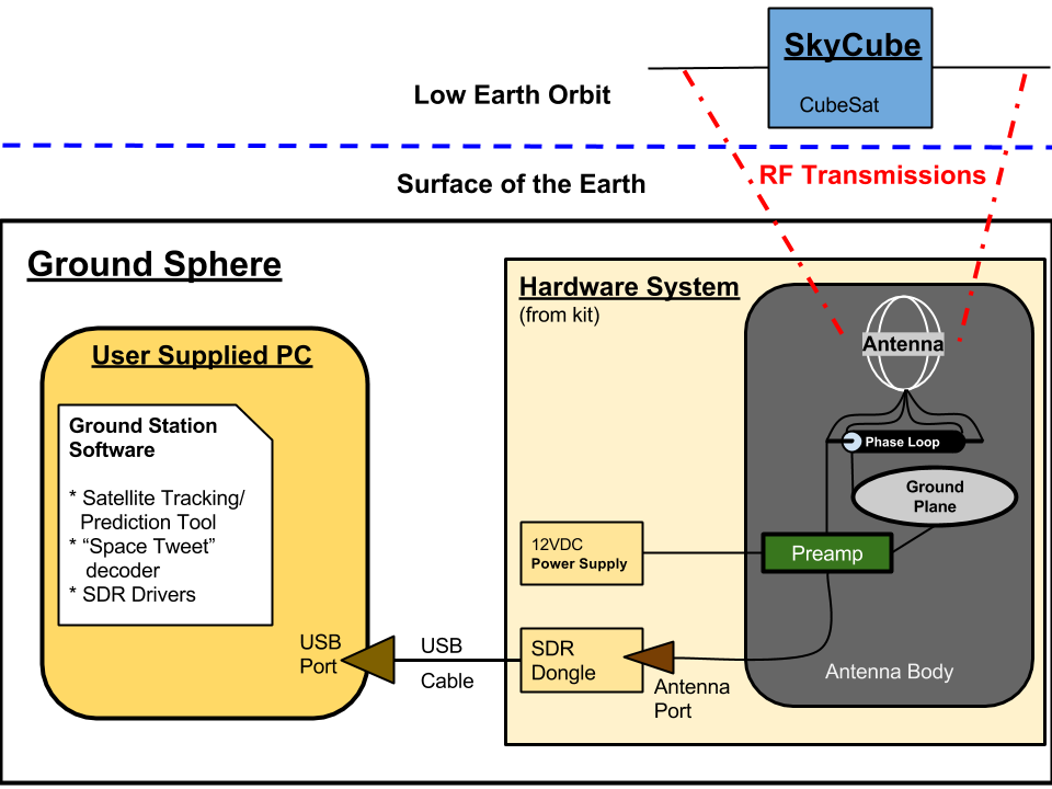
Ground Sphere Block Diagram v0.2
The following block diagram describes the key components of the Ground Sphere. Note the boundary between the kit supplied hardware and the user supplied PC.
( SVG Format )
Ground Sphere BoM v0.2
Ground Sphere v0.2 BoM
Ground Sphere Budget v0.2
Overview
The materials cost should be kept under $100 to limit the retail cost of the kit. There are currently three prototypes planned. The project budget should cover all three prototypes plus overage. To that end, the threshold project budget (max) is $500 and the objective is $400.
Antenna Cost Estimates
| Item |
Cost (Minus Shipping) |
Link |
| Antenna Body |
$0.92 |
|
| Coupling Sections |
$0.20 |
|
| Base Adapter |
$6.61 |
|
| Base |
$2.50 |
|
| Coupler |
$2.50 |
|
| End Cap |
$1.51 |
|
| Aerial Terminals |
$7.96 |
|
| Aerial Terminal Retaining Screws |
$0.28 |
|
| Aerial Terminal Retaining Nuts |
$0.16 |
|
| Ring Terminals |
$0.36 |
|
| Ring Terminal |
$0.12 |
|
| Ring Terminals |
$0.24 |
|
| Aerials |
$0.20 |
|
| Antenna Line RP-SMA Female Bulkhead to Pigtail |
$1.75 |
|
| Antenna to Preamp Line RP-SMA Male to Male |
$3.50 |
|
| Preamp to SDR Line RP-SMA Male to MMCX Male |
$3.50 |
|
| Phasing Loop |
$5.00 |
|
| Ground Plane Fabric |
$1.25 |
Link |
| Ground Plane Backing |
$0.99 |
Link |
| Conductive Thread |
$1.00 |
Link |
| Rubber Feet |
$0.99 |
|
| Total |
$41.54 |
|
Radio Cost Estimates
| Item |
Cost (Minus Shipping) |
Link |
| RTL2832U Software Defined Radio (SDR) Dongle |
$9.75 |
Link |
| ATF54143 Pre-Amplifier |
$35.00 |
Link |
| 2.1mm DC Power Jack |
$3.49 |
|
| Small Heat Shrink Tubing for Power Connection |
$0.05 |
|
| Total |
$48.29 |
|
Ground Sphere Initial Questions v0.2
Project Background Questions
BQ1. Why are we making this?
BA1. The Ground Sphere CubeSat Ground Station is being built specifically to receive ""tweets from space" which will be broadcast by the SkyCube CubeSat. A side effect of having such a low cost and easy to use ground station is the educational opportunities in areas including satellite orbits, radio technology, telecommunications, and programming.
BQ2. Who is this for?
BA2. The Ground Sphere CubeSat Ground Station is for SkyCube backers, students, teachers, scouting troupes, space enthusiasts, and anyone who wants to directly experience satellite communications and participate in the SkyCube mission.
BQ3. How will this be used?
BA3. Ground station operators will use the ground station and its accompanying software to:
- Predict when the SkyCube (and other satellites) will be flyover the ground station site
- Use the Software Defined Radio (SDR) to receive the radio transmissions from SkyCube (and other satellites operating on the nearby frequencies)
- Decode the data packets from the SkyCube to read the "tweets" from space
BQ4. Who's going to build this?
BA4. The designs will be open so that anyone, without necessarily a technical education in amateur radio or satellite operations, would be able to build and operate a Ground Sphere CubeSate Ground Station. Note, the first kits will be built by SkyCube KickStarter backers.
Technical Requirement Questions
TQ1a. What features does it need to have (now)?
TA1a. The project needs to:
- Predict when the SkyCube satellite will flyover the ground station and be within signal reception range
- Receive radio signals on 915 MHz
- Decode BPSK-modulated, unencrypted AX.25 data packets sent at 9600 baud
- Be easy to assemble from kit components and only require simple tools (screw drivers, pliers, wrenches, etc) for assembly
- Have low shipping costs for the packaged kit
- All software required to operate the ground station must run on a Windows PC
- The ground station radio must connect to the ground station computer through a commonly available port (for example: USB)
- The ground station hardware should minimize the opportunity for mechanical failures (from things such as broken connectors or a lack of strain relief)
- The ground station needs to account for Doppler shift during satellite flyovers
TQ1b. What features does it need to have (later)?
TA1b. In the future, the project (or related projects) may need to:
- Predict when other satellites will fly over the ground station and be within signal reception range
- Decode other data formats commonly used by CubeSats
- Share radio signal with other users over Internet connections, so users can listen to satellite signals remotely
- All software required to operate the ground station must run on Windows, OS X, and Linux
TQ2. What are the legacy requirements?
TA2. To maintain compatibility with other projects, the system should:
Project Requirement Questions
PQ1. How many do we want to make?
PA1. As an open source hardware kit, the long term objective is to promote and sell as many ground station kits to as large of an audience (schools, scouting troupes, makerspaces, space enthusiasts, etc) as possible. However, the narrow focus on supporting SkyCube operations with the Ground Sphere may limit the number of kits which will be sold for this specific ground station, especially since the SkyCube is going to be on orbit for a very limited period of time. The sales lifetime of this specific kit (and in turn the number of kits we will want to sell) will depend on how many other satellites there are to observe in the same frequency range as the SkyCube. Note, there are approximately 2700 backers of the SkyCube KickStarter, of which Southern Stars is committed to delivering ground stations to between 20 and 30 backers. This gives a minimum number of ground stations to be built of 30 +/- 5, which would cover the minimum backers and a handful for Mach 30's use.
The timing of the project may also limit the scale of the initial run Mach 30 can produce. This decision will be revisited later in the development process (after the second prototype) to allow the development team to address the manufacturing logistics.
PQ2. What is the budget?
PA2. The materials cost should be kept under $100 to limit the retail cost of the kit. There are currently three prototypes planned. The project budget should cover all three prototypes plus overage. To that end, the threshold project budget (max) is $500 and the objective is $400.
PQ3. What is the timeline?
PA3. The timeline for this project is dictated by the SkyCube launch and deployment timeline. SkyCube is currently scheduled to be launched in December 2013, with deployment from the ISS in Q1 or Q2 of 2014. Southern Stars has stated they would be comfortable with a February 2014 delivery date for the kits. This gives a kit completion date of early January 2014 to give enough time to spool up manufacturing and shipping for the February due date.
PQ4. What waste products will be produced by the manufacture and/or operation of this?
PA4. TBD
Ground Sphere Kit Assembly Instructions v0.2
Introduction
These instructions are designed to help you assemble a Ground Sphere ground station kit once it has arrived.
Tools
- Common screwdriver
- Optional: 8mm combination wrench
- Optional: toothpick or dental pick
Materials
- 1 ea Upper Assembly, Ground plane, and ¾”PVC to ½ NPT adapter (previously assembled)
- 1 ea Lower Assembly (previously assembled)
- 2 ea Aerial Loops
Safety issues
Care must be taken when working with hand tools.
Product or Outcome
A complete Ground Sphere Mk2 Ground Station.
Procedure
- Remove all parts from the box and protective coverings.
- Using a common screwdriver, unscrew the outlet cover mounting screws and remove the outlet cover (ANT04).
- Insert the antenna line (ANT13) SMA connector through the hole in the outlet cover (ANT04).
- Thread the outlet cover (ANT04) on to the upper assembly threads, twisting until moderately tight.
- Connect the antenna line (ANT13) SMA connector to the input connector of the preamp (RAD02).
- Finger tight should be fine, but if the clearance is too tight to get access, use an 8mm combination wrench to turn the connector.
- Do not tighten beyond lightly snug, or the SMA connector may snap off the preamp (RAD02).
- Using a common screwdriver, reattach the outlet cover (ANT04) to the base.
- Place the ground plane assembly over the purple coupling section.
- Insert the purple coupling section into the upper assembly and press until snug.
- Loosen all four aerial retention screws on the aerial terminals (ANT07).
- Using a toothpick to push it through from the bottom, thread the conductive thread tail into the marked aerial terminal.
- Insert the aerial ends into opposing aerial terminals, taking care not to drop the ground lead from the ground plane.
- Tighten the aerial retention screws on the aerial terminals (ANT07).
- View the assembled unit from the top and adjust the loops to be vertical and perpendicular to each other.
Ground Sphere Meeting Minutes
v0.1
v0.2
- TODO: Add new minutes here
Ground Sphere Operating Manual v0.2
Setup
Instructions on connecting the antenna, software defined radio dongle, and computer together to operate the ground station go here. Note, be sure to talk about if the antenna should be mounted outside and if so, how.
Hardware
There are two pieces of required hardware. The antenna/receiver unit and a user provided laptop
User provided laptop, minimum system requirements
- Windows 7 operating system
- 1GHz single core CPU
- 1GB RAM
- Open USB port
To install the antenna/receiver
Software
There are two pieces of software needed to operate the ground station. The satellite tracking software, GPredict, and the AX.25 decoder, SeeDeR.
GPredict Operating Instructions
The user manual for gpredict is available at http://sourceforge.net/projects/gpredict/files/Gpredict/1.3/gpredict-user-manual-1.3.pdf/download. Chapter 2 covers the basic operating instructions.
SeeDeR Operating Instructions
- Ensure you have an RTL-SDR device drivers and the SeeDeR installed correctly via the Software Installation instructions.
- Launch SeeDer by running the SeeDeR.exe from the folder where you installed SeeDeR
- If the RTL-SDR device is detected, you should see a moving waterfall display
- You may wish to tune to an FM station to check basic performance:
- Type a typical FM frequency (say, 100,100,000) into the "Center" box.
- Click in the waterfall display to hit the exact center of a station (or type the frequency into the "Frequency" box).
- Select "WFM" under "Demodulation", and you should hear FM audio, and possibly see RDS data.

- To pick up AX.25 data:
- Select "AX.25" under "Demodulation"
- Select the proper baud rate and modulation under "AX.25 Settings"
- Settings for SkyCube:
- Uplink: 450 MHz, 9600 baud, 2FSK modulation
- Downlink: 915 MHz, 57600 baud, BPSK modulation
- Tweets: 915 MHz, 9600 baud, BPSK modulation
Extra notes:
- The sample rate under "Device Settings" can be left at the default 2.048 MS/s. Higher settings do not increase performance, and have worse frequency response.
- If you have a high performance computer, select "Very High" for visualization quality.
- You may have to play with the ACG and gain settings for proper reception, especially for local transmissions (at high power levels, the input data gets clipped unless the gain is lowered).
- Try clicking the edges of the waterfall window, as well as clicking and dragging.
- Bookmarks allow you to save most of the settings and quickly swap to them
- SeeDeR should work fine with more than one RTL-SDR device. Settings are associated with a device, so you can see uplink and downlink data simultaneously.
Ground Sphere Preliminary Design v0.1 (OUTDATED)
Introduction
This document covers the preliminary design decisions for the Ground Sphere ground station. The document includes three sections: technical background on SkyCube's radio, hardware design of Ground Sphere, and software design of Ground Sphere. The design is structured in parallel with the Requirements Document to ensure all requirements are satisfied.
SkyCube Radio Details
SkyCube uses a Colony 2 (CII) radio from AstroDev. The specific radio is the Boeing variation as documented in the following PDF (CII_Specification_08042010.pdf).
The SkyCube radio operates at 915 MHz with a transmit power of 2 W. It has an omni-directional antenna which adds negligible gain.
Hardware Design of Ground Sphere
- TR 1.1 Enable users to receive "space tweets"
- TR 1.1.2 Receive radio signals on 915 MHz (link budget)
- Antenna
- Dimensions (source)
- Phasing line: 2.7745" of RG-62 90 ohm coax cable
- Ground plane: 6.3" diameter disk of conductive rip stop fabric
- Ground plane radial arms: 2.3925" of rigid material (need not be conductive)
- Aerial length (circumference): 13.7075" of 12ga copper wire or better
- Distance between bottom of aerials and ground plane: 1.6475"
- Preamp
- RTL2832U SDR
- TR 1.2 Be easy to assemble from kit components
- TR 1.2.1 Time to assemble
- Ground station will be shipped as a kit
- TR 1.2.2 Tools for assembly
- Preamp will ship already assembled, ground station structure will include all drill holes and all other component fabrications steps
- TR 1.3 Have low shipping costs for the packaged kit
- <insert max dimensions here?>
- TR 1.4 Operate using a modern Windows PC
- TR 1.4.3 Hardware must connect to PC using standard port(s)
- The SDR connects to host computer through USB 2.0
- TR 1.5 Hardware must be robust
- All connectors will be designed to ensure long life (internally mounted, have adequate strain relief, etc)
- PR 2.1 Budget
- PR 2.1.1 Unit cost
- <insert current materials cost here from BoM>
Software Design of Ground Sphere
- TR 1.1 Enable users to receive "space tweets"
- TR 1.1.1 Predict SkyCube flyover opportunities
- TR 1.1.2 Receive radio signals on 915 MHz
- SeeDeR software (provided by Southern Stars) can tune SDR to 915 MHz
- TR 1.1.3 Decode "space tweet" message from SkyCube
- SeeDeR software (provided by Southern Stars) can decode the BPSK-modulated, unencrypted AX.25 data packets sent at 9600 baud "space tweets" sent out by SkyCube
- TR 1.1.4 Account for Doppler shift
- SeeDeR software (provided by Southern Stars) will be updated to account for Doppler shift
- TR 1.4 Operate using a modern Windows PC
- TR 1.4.1 Software must run on Windows
- GPredict runs on Windows 7
- SDR drivers <get link from Aaron> run on Windows 7
- SeeDeR runs on Windows 7
- TR 1.4.2 Software must be easy to install
- GPredict includes a Windows installer
- SDR drivers include a Windows installer
- Southern Stars will provide a Windows installer for SeeDeR
Ground Sphere Requirements v0.2
Technical Requirements
TR 1.1 Enable users to receive "space tweets"
TR 1.1.1 Predict SkyCube flyover opportunities
The Ground Sphere will include software which predicts when the SkyCube satellite will flyover the ground station and be within signal reception range
TR 1.1.2 Receive radio signals on 915 MHz
The Ground Sphere will receive radio signals on 915 MHz with sufficient gain to enable decoder software to decode the "space tweet" text message
TR 1.1.3 Decode "space tweet" message from SkyCube
Decode BPSK-modulated, unencrypted AX.25 data packets sent at 9600 baud
TR 1.1.4 Account for Doppler shift
The Ground Sphere needs to account for Doppler shift during satellite flyovers
TR 1.2 Be easy to assemble from kit components
TR 1.2.1 Time to assemble
The Ground Sphere will take no longer than 60 minutes (threshold)/30 minutes (objective) to assemble by an average maker
TR 1.2.2 Tools for assembly
The Ground Sphere will only require simple tools (screw drivers, pliers, wrenches, etc) for assembly
TR 1.3 Have low shipping costs for the packaged kit
The Ground Sphere kit will cost no more than $15 (threshold)/$7.50 (objective) to ship by ground across the USA.
TR 1.4 Operate using a modern Windows PC
TR 1.4.1 Software must run on Windows
The Ground Sphere software must run on Windows 7 or Windows 8 (32bit or 64bit)
TR 1.4.2 Software must be easy to install
The Ground Sphere software must ship in a Windows installer
TR 1.4.3 Hardware must connect to PC using standard port(s)
The ground station radio must connect to the ground station computer through a commonly available port (for example: USB)
TR 1.5 Hardware must be robust
The Ground Sphere hardware should minimize the opportunity for mechanical failures (from things such as broken connectors or a lack of strain relief)
Project Requirements
PR 1.1 Number to produce
The Ground Sphere design must enable the production of at least 30 +/- 5 v1.0 kits by volunteers in one or more makerspaces
PR 2.1 Budget
PR 2.1.1 Unit cost
The materials cost must be under $100 per kit.
PR 2.1.2 Development cost
The project budget (covering three prototypes) must be no more than $500 (threshold)/$400 (objective)
PR 3.1 Timeline
Version 1.0 of the Ground Sphere will be ready for kit production no later than Feb 14, 2014.
Resources
- Antenna Design
- Software Defined Radio Links
- Satellites Operating at/near SkyCube's frequency (915MHz)
- Publicity Resources
- Analysis Resources
- Extending Ground Sphere's Concept
Ground Sphere Safety Procedures v0.2
Introduction
Since this device is receive only, there are no operational safety procedures outlined at this time. This document may be modified at any time, and a notice should be posted to the forums when that happens. Check back to this document frequently to ensure that you have the latest safety information.
Additional Safety Information
The American Radio Relay League safety committee has safety information and explanations that can be reviewed before operating Ground Sphere.
Ground Sphere Schematics and PCB Files v0.2
ATF54143 Pre-amplifier
The original source material can be found here


Ground Sphere CubeSat Ground Station
User Manuals
End user manuals, including how to assemble from kit and operating instructions for predicting flyovers and receiving "space tweets".
Documentation
Full OSHW project documentation - covers component acquisition and assembly, packaging of kits, and other project level documentation needed to replicate the Ground Sphere from source.
Systems Engineering Process
Full OSHW project design documentation - covers design from concept through final design.
- Initial Questions
- Requirements Document
- Block Diagram
- Budget
- Timeline
- Preliminary Design
- Detailed Design
- Design Review
- Procurement
- Manufacture
- Integration
- Testing
- Disposal
- Meeting Minutes/Notes
- Resources/Links
Ground Sphere Software Installation v0.2
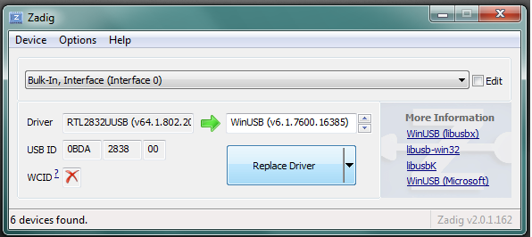
Install SDR Dongle Drivers (Zadig)
- Plug the SDR dongle into a USB port on your Windows PC
- Download the dongle driver installer from Zadig.
- Run the installer and select Options > List All Devices
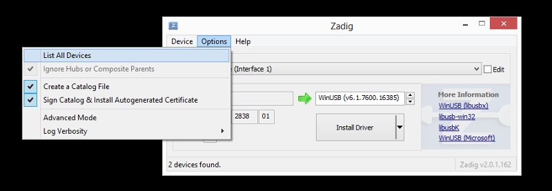
- Pull down the interfaces drop-down and select Bulk-In, Interface (Interface 0)
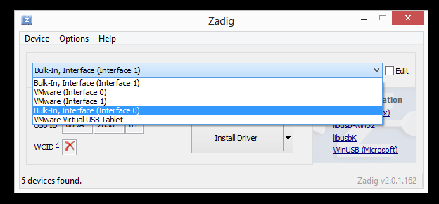
- Click the Install Driver or Replace Driver button (which one you see will depend on previous driver installations)
Note, if after installation you are unable to detect the SDR Dongle in SeeDeR (see this "forum post": for an example), then you should try uninstalling the drivers and starting over following these steps.
- Open the Device Manager in Windows (Click the Start button and type in "device manager" and hit enter)
- Find the SDR dongle in the Device Manager (it will be listed either under "Sound, video and game controllers" as REALTEK 2832U or under "Universal Serial Bus devices" as Bulk-in, Interface (Interface 0)

- Right-click on the SDR device in Device Manager and select Uninstall

- The Uninstall Device dialog will open, be sure to select the Delete driver software check box then click OK
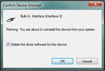
- When the driver finishes uninstalling, remove the USB Dongle, then start the installation process over again, making sure to use the same USB port as before
Install SDR Controller Software (SeeDeR)
Note, you will need 7-zip installed to unzip the SeeDeR executable.
- Download the SeeDeR zip file and the MSVC 2012 runtime library
- Run the MSVC 2012 installer (vcredist_x86_vs2012.exe)
- Use 7-zip to unzip all SeeDeR files into a directory you can access when you want to use the ground station
Install Orbital Tracking/Prediction Software (GPredict)
- Download GPredict from http://sourceforge.net/projects/gpredict/files/Gpredict/1.3/gpredict-win32-1.3-3.zip/download.
- Unzip the downloaded zip file into a folder
- Follow the directions in the README.txt document in the unzipped file.
Ground Sphere Software Source Code v0.2
In order to download the latest source code for the SeeDeR SDR/Packet Decoding software, you will need a subversion client.
Once you have used the client to check the code out, the top level directory will be groundsphere and the most current production version will be in the trunk directory.
There will also be milestone versions available for download from DMSF . These versions will not necessarily be the most up-to-date though.
For instructions on how to use the software, please see the Operating Manual
Ground Sphere Testing v0.2
This document contains Test and Evaluation Master Plan (TEMP) for both the prototype and production QA. The prototype plan is designed to ensure the design meets with the specified requirements. The QA plan is designed to ensure kits meet quality requirements before being shipped to a customer.
Prototype TEMP
Prototype test and evaluation cover the full range of ground station functions. This includes satellite tracking, signal acquisition, "space tweet" decoding. Additionally, the assembly process will be tested in later prototypes. Note, test numbers correspond to the requirement the test verifies (for example, Test 1.1.2 verifies requirement TR 1.1.2). TEMP was developed at the #EngineerSpeak Hangout on Dec 5, 2013.
| Requirement |
Requirement Title |
Verification Method |
Version |
Status |
Notes |
| TR 1.1.1 |
Predict SkyCube flyover opportunities |
Demonstration |
v0.1 |
Pass [2013.12.05] |
Using 3rd party tool, GPredict which meets requirement assuming ground station location and SkyCube TLE are known |
| TR 1.1.2 |
Receive radio signals on 915 MHz |
Test |
v0.1 |
TBD |
Test 1.1.2 Instructions |
| TR 1.1.3 |
Decode "space tweet" message from SkyCube |
Test |
v0.2 |
TBD |
Lab tests at Southern Stars using v0.1 Ground Sphere and backup SkyCube to confirm correct reception and decoding of "space tweets" |
| TR 1.1.4 |
Account for Doppler shift |
Demonstration |
v0.2 |
TBD |
Prereq: Test 1.1.2; show ground station software tunes SDR for doppler shift and that this provides longer signal reception than without feature turned on when observing NPS cubesat |
| TR 1.2.1 |
Time to assemble |
Demonstration |
v0.2 |
TBD |
Juli & Greg will assemble a v0.2 kit at Quelab and time the assembly process |
| TR 1.2.2 |
Tools for assembly |
Inspection |
v0.2 |
TBD |
Inspect kit assembly instructions to verify the list of tools required meets the spec |
| TR 1.3 |
Have low shipping costs for the packaged kit |
Test |
v0.2 |
TBD |
Collect components and measure required volume, compare to published shipping rates |
| TR 1.4.1 |
Software must run on Windows |
Demonstration |
v0.2 |
TBD |
Install and run software on Win7 and Win8 x86 and 64bit versions |
| TR 1.4.2 |
Software must be easy to install |
Demonstration |
v0.2 |
TBD |
Show there is an installer and run it to verify the software installs correctly |
| TR 1.4.3 |
Hardware must connect to PC using standard port(s) |
Inspection |
v0.1 |
Pass [2013.12.05] |
Design documentation specifies use of USB SDR module -> connection to ground station computer is a USB connection |
| TR 1.5 |
Hardware must be robust |
Analysis |
v0.1 |
TBD |
During the design phase from v0.1 to v0.2 look at each component and determine potential failure modes and whether they need mitigation |
Quality Assurance TEMP
This set of instructions will be used to verify that each of the Groundsphere kits will be delivered in a working condition.
Hardware Assembly
- Verify the parts fit together properly and kit assembly instructions have been followed
- Purple primer should not be visible on the outside of the antenna body.
- The holes in the coupling section (ANT02) should be 90 degrees apart and in the center of the part.
- The RF conductors on the phasing loop and antenna line should not be broken (open) or shorted. This may be inspected through removal of the top end cap.
- Ensure the bolts retaining the aerial lugs are tight.
- Inspect the heat shrink tubing covering the ends of the power jack wires for good coverage and mechanical connection.
- Ensure all holes in the lower enclosure have a plug, power, or USB cable in them.
- Ensure all labels have been afixed to the lower assembly.
- Inspect the sealant around the USB connection. Make sure it has adequate coverage, extending through the hole, with no excessive amount or drips. It should conform to the ends of the hole and cable smoothly, and never enter the connector.
- The SDR should be fully seated in the end of the USB connector.
- The preamp circuit board should be firmly attached to the SDR with enough room the thread the antenna line on to the input jack of the preamp.
- Rubber feet should be attached to the bottom of the base.
- Aerial loops should be smoothly circular with stripped ends bent at 90 degrees.
- Verify electrical connectivity and proper function
- The ground plane should be smooth and conductive, measuring between 0 and 500 ohms from the pigtail of conductive thread and the outer rim of the conductive fabric.
- When plugged into the test power supply, the preamp should not draw more than 50mA at 12VDC.
- When the USB cable is plugged into the test PC, the PC should recognize the SDR. It should not attempt to install a different driver or not show up in Zadig at all.
- The device under test should see the simulated satellite signal strongly at a strength of 0dB at a range of 2-3 meters.
- Upon passing all QA inspections, the inspector shall write their initials and the serial number on the inside of the upper assembly, indicating acceptance.
- Verify the completeness of the kit
The kit must include the following:
- Base assembly, 1 ea.
- Aerial loops, 2 ea.
- Upper assembly, 1 ea.
- Screws to attach the upper and lower assemblies, 2 ea.
- Rubber gasket which sandwiches between the upper and lower assembly, 1 ea.
- Ground plane assembly, 1 ea.
- 12vdc AC adapter, 1 ea.
- A software CD, 1 ea.
- An instruction booklet, 1 ea.
Test 1.1.2 Instructions
Test Hardware
Test 1: Lab Test
Lab test using low power transmitter at 915 MHz to confirm signal reception and system gain (not an AX.25 signal, but close enough). These instructions assume that the receiver is already assembled and most recent software is installed. If not, accomplish the next 2 steps.
- Follow the instruction for "GroundSphere Kit assembly"
- Follow the instructions for Operations Manual - "Getting Started and Set up"
Test Date:
04JUN14@2057-2146MST Test Location: MSL / Issyroo Lab, Walsenburg, CO
Record Test Conditions:
23C ambient, indoor test, metal fixtures to hold test gear, moderately noisy RF environment, Cell phones off and batteries removed.
Additional Tools Needed:
Tape Measure
Safety concerns:
Standard lab safety; standard procedures reviewed.
Outcome:
- Partial verification of technical requirement 1.1.2,
- Confirmation of Ground Sphere performance in best case laboratory conditions
- Confirmation of Ground Sphere performance in simulated orbital conditions
Instructions:
- [X] Turn on computer
- [X] Turn on the transmitter
- [X] Plug the GroundSphere USB data connector into an open USB port
- [X] Plug the GroundSphere power cord into a standard 120v power outlet
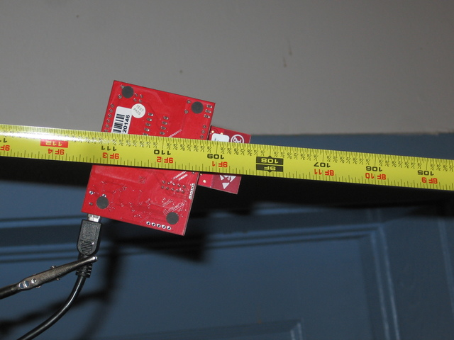
- [X] Measure and record the distance between transmitter and receiver: 1 meter Used standard tape measure at 36 inches
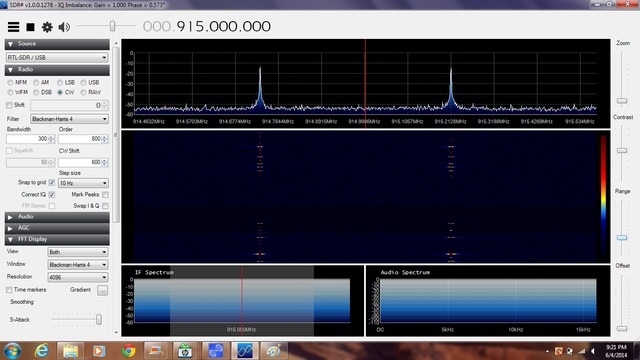
- [X] Launch the SeeDeR version 0.1 software Used SDR# for the ability to freeze the display
- [X] Tune the SeeDeR version 0.1 software to receive 915 MHz
- [X] Position the cursor (red vertical bar) at 915 MHz on the horizontal axis
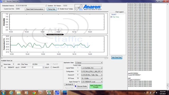
- [X] Record the noise floor signal level: -53.89 dBm
- [X] Tune the transmitter to 915 MHz. Instructions
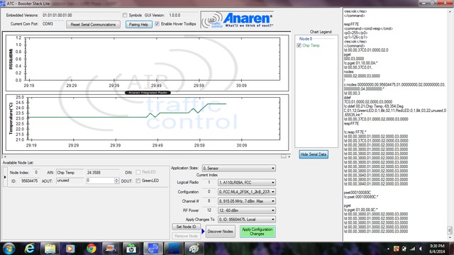
- [X] Set transmitter power to -20dBm. Instructions _NOTE: (This is a reasonably strong terrestrial signal, and is an unrealistically high power to expect from SkyCube. See Lab Test Link Budget figures here
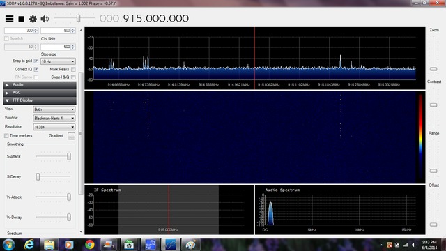
- [X] Observe and capture/record the transmitted signal received by GroundSphere. Set to -18dBm as closest equivalent
- [X] Position the cursor (red vertical bar) at the center peak of the displayed radio signal on the horizontal axis
- [X] The signal should be plainly obvious as a strong peak above the noise floor. If this is not the case, abort the test and troubleshoot. Signal was measured at -11.91dBm, 41.98dBm above the noise floor
- [X] Measure and move the transmitter 3 meters from the GroundSphere antenna ensuring a clear line of sight.
- [X] Set the transmitter power level to -60dBm. NOTE: (at this power level, the intent is to get as close as possible to the signal strength that we expect to receive form SkyCube as it flies directly overhead of the antenna, given its orbital parameters. See the link budget )
- [X] Observe the transmitted signal received by GroundSphere
- [X] Position the cursor (red vertical bar) at the center peak of the displayed radio signal on the horizontal axis
- [X] Record the radio signal level: -33.88 dBm
- [X] Subtract the noise floor figure recorded earlier from the radio signal level recorded in the step above.
- [X] Record the difference between the signals: 20.01 dB
- [X] The difference between the signal and noise floor should be at least 17dBm. If this is not the case, abort the test and troubleshoot.
NOTE: All tests have been completed 3 times with result variances below 0.01%. Screenshots and pictures are included below, and the raw I and Q dataset is available on the shared project Google Drive Folder. Warning: it is over 220MB in size and only works with an SDR program like GNU Radio, SDR#, or SeeDeR. The audio file is linked below as well.
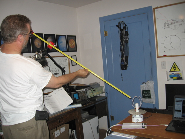
One meter test setup (Step 5)

Noise floor measurement (Step 9)
Satellite Simulator Settings (Step 11)
Strong signal test (Step 12)
Three meter test setup (Step 15)
Satellite simulator settings (Step 16)
Final lab test (Step 17)
Audio output of final lab test
Raw baseline (I/Q) data of final lab test
LAB TEST PROCEDURE COMPLETE
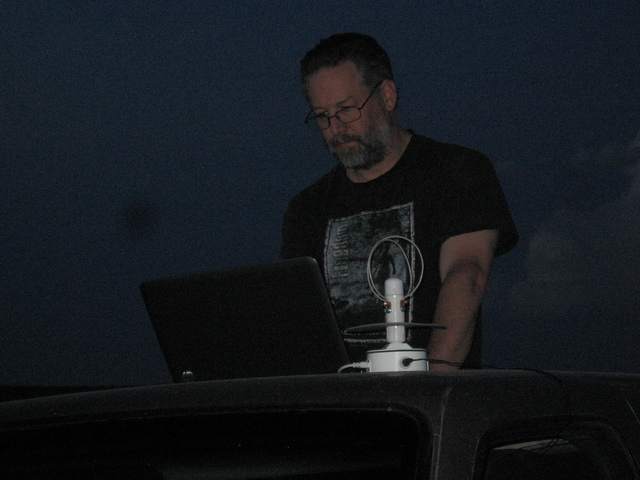
Test 2: Field Test
Long range field test using low power transmitter at 915 MHz to verify the predicted link budget (which comes from <insert link to spreadsheet> analysis) and confirm signal reception. It is recommended to conduct this test with at least 2 individuals. These instructions assume that the receiver is already assembled and most recent software is installed. If not, accomplish the next 2 steps.
- Follow the instruction for "GroundSphere Kit assembly"
- Follow the instructions for Operations Manual - "Getting Started and Set up"
Test Date:
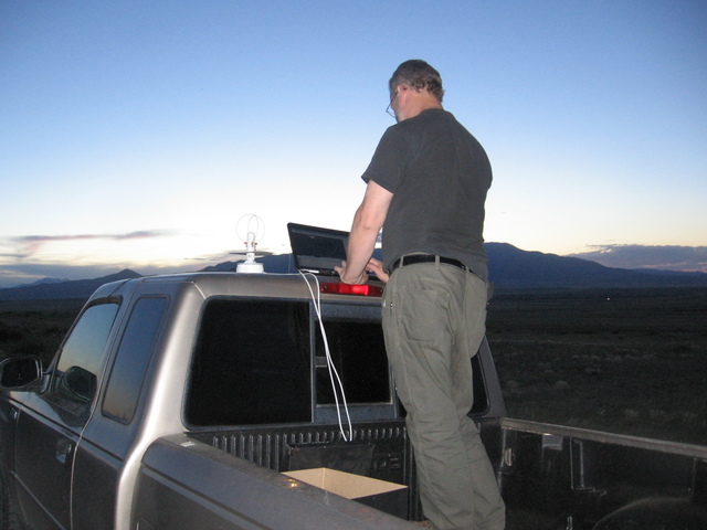
20JUN2014@2115-2145MST Test Location: MSL / Issyroo RF test range at 37°43'04.8"N 104°47'16.9"W, 10 miles North of Walsenburg, CO
Record Test Conditions:
26C ambient, outdoor test with full horizon to horizon window, ground station mounted to truck roof, fairly clean RF environment, though some RF energy may come from activities at a small airport located at 37°41'49.2"N 104°47'34.8"W. No planes were observed to be in operation. Cell phones were turned off and batteries removed.
NOTE: This series of tests were run at 0 degrees elevation, which means that the performance is higher in the cone shaped reception pattern beginning at 30 degrees elevation. Computer simulation places the tested area at -5dB compared to the peak lobe with a small amount of interference from the close proximity to the ground (ground effect). This means that actual performance will be higher for any satellite within reception range. The reason for performing these tests in this manner was that in the low light conditions, it was against the use agreement for the facility to climb the tower.
Additional Tools Needed:
Laptop computer meeting or exceeding the minimum system requirements.
Portable table or truck bed (on which to set up receiver equip and computer)
Access to 120V a/c power for preamp (generator or car inverter) or DC adapter (vehicle power jack to 2.1mm preamp power jack).
Tape measure or distance finding equipment (GPS?)
Safety concerns:
Weather caution
Traffic caution
Portable power for equipment(?)
Outcome
- Partial verification of technical requirement 1.1.2,
- Confirmation of Ground Sphere performance in optimal fielded conditions
- Confirmation of Ground Sphere performance at a far distance to simulate orbital conditions
Instructions:
Mission Control Set Up
- [X] Set up receiver and computer on portable table or in a vehicle with the antenna outside.
- [X] Turn on computer
- [X] Plug the GroundSphere USB data connector into an open USB port
- [X] Plug the GroundShpere power cord into a standard 120v power outlet Used automotive DC power jack, vehicle supply measured 13.9VDC
- [X] Launch the SeeDeR version 0.1 software Used SDR# for the ability to freeze the display
- [X] Tune the SeeDeR version 0.1 software to receive 915 MHz
- [X] Position the cursor (red vertical bar) at 915 MHz on the horizontal axis
- [X] Record the noise floor signal level: -42.6 dBm Seems to be fairly noisy even though the location is away from most sources. Grounding issue?
- [X] Move to a distance 2650 meters away from the receiver set up with a clear line of sight, then set up the transmitter
- [X] If not exactly the above distance, record the distance between transmitter and receiver (in m): N/A
Remote transmit site Set Up
- [X] Power on and tune the transmitter to 915 MHz. Instructions
- [X] Set transmitter power to 0dBm NOTE: (This is a reasonably strong terrestrial signal, and is an unrealistically high power to expect from SkyCube)
- [X] Tune the SeeDeR software to receive 915 MHz
- [X] Observe and capture/record the transmitted signal received by GroundSphere from the test transmitter
- [X] Position the cursor (red vertical bar) at the center peak of the displayed radio signal on the horizontal axis
- [X] The signal should be plainly obvious as a strong peak above the noise floor. If this is not the case, abort the test and troubleshoot.
- [X] Set the transmitter power level to -20dBm. _NOTE: (at this power level, we are simulating the signal that we expect to receive form SkyCube as it flies directly overhead of the antenna, given its orbital parameters. See the Outdoor Test Link Budget here
Testing
- [X] Observe and capture/record the transmitted signal received by GroundSphere from the test transmitter
- [X] Position the cursor (red vertical bar) at the center peak of the displayed radio signal on the horizontal axis
- [X] Record the radio signal level: -22.3 dBm
- [X] Subtract the noise floor figure recorded earlier from the radio signal level recorded in the step above.
- [X] Record the difference between the signals: 20.3 dBm
- [X] The difference between the signal and noise floor should be at least 17dBm. If this is not the case, abort the test and troubleshoot.
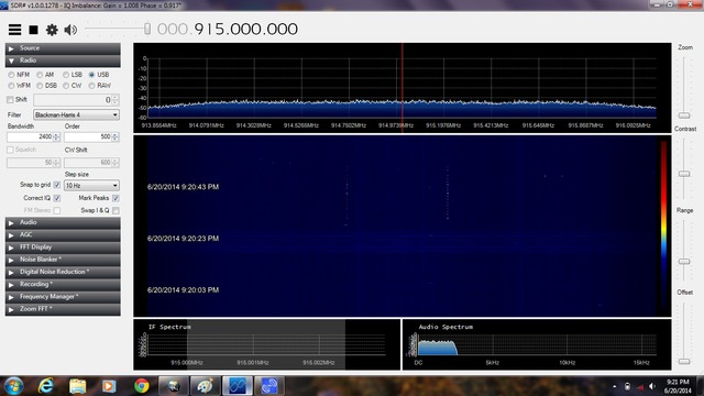
Setting up SDR# for the field test
<insert image of transmitter setup> Camera battery failed after taking above picture.
<insert screenshot image of computer screen showing high power 915 MHz signal> None taken during the procedure listed above. Signal showed around -9dBm.
Low power test showing peaks. (Testing step 1)
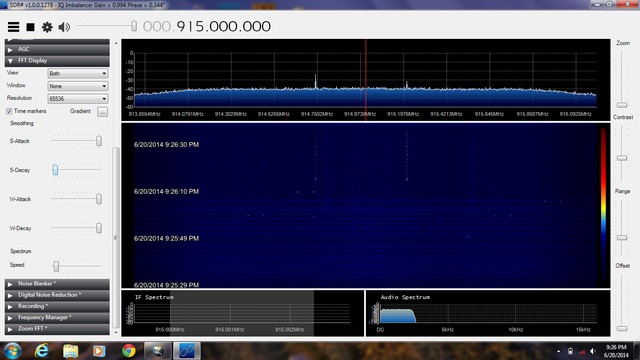
Low power test East to West. Peaks shown in waterfall display.
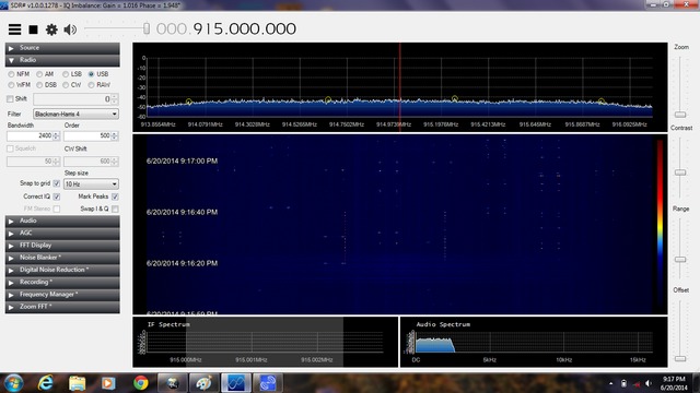
Low power test West to East. Peaks shown in waterfall display.
FIELD TEST PROCEDURE COMPLETE
Test 3: From Orbit Test
Acquire signal from orbiting cubesat operating on 915 MHz (NPS just launched two cubesats which use the same radio and configuration as SkyCube). Orbital prediction software will need to be used to calculate the appropriate timing for this test. It is only possible to conduct the steps below in anticipation of a 915 MHz signal source flying overhead. These instructions assume that the receiver is already assembled and most recent software is installed. If not, accomplish the next 2 steps.
- Follow the instruction for "GroundSphere Kit assembly"
- Follow the instructions for Operations Manual - "Getting Started and Set up"
Test Date:
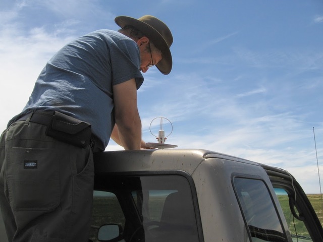
20JUN2014@2055-2110MST Test Location: MSL / Issyroo RF test range at 37°43'04.8"N 104°47'16.9"W, 10 miles North of Walsenburg, CO
Record Test Conditions:
28C ambient, outdoor test with full horizon to horizon window, ground station mounted to truck roof, fairly clean RF environment, though some RF energy may come from activities at a small airport located at 37°41'49.2"N 104°47'34.8"W. No planes were observed to be in operation. Cell phones were turned off and batteries removed.
Tools Needed:
Ground Sphere test rig
Computer meeting min system reqs
Skycube satellite pass within range of receiving station.
Safety concerns:
Weather caution
Traffic caution
Outcome:
Verification and completion of Technical requirement 1.1.2
Instructions:
- [X] Set up receiver and computer on portable table or in a vehicle with the antenna outside
- [X] Turn on computer
- [X] Plug the GroundSphere USB data connector into an open USB port
- [X] Plug the GroundShpere power cord into a standard 120v power outlet
- [X] Launch the SeeDeR version 0.1 software
- [X] Tune the SeeDeR software to receive 915 MHz
- [X] Position the cursor (red vertical bar) at 915 MHz on the horizontal axis
- [X] Record the noise floor signal level: -42.4 dBm Seems to be fairly noisy even though the location is away from most sources. Grounding issue?
- [X] Await Skycube satellite pass as predicted by gpredict or other prediction software
- [X] Observe and capture/record the transmitted signal received by GroundSphere
- [X] Record the closest approach as shown by the polar plot (sky view) on GPredict: 86.00 degrees elevation at 21:03:29
- [X] Position the cursor (red vertical bar) at the center peak of the displayed radio signal on the horizontal axis
- [X] Record the radio signal level: N/A No signal received. Not even a twitch or blush on the screen which would have occurred even if the signal was too weak to be decoded.
- [X] Subtract the noise floor figure recorded earlier from the radio signal level recorded in the step above
- [X] Record the difference between the signals: N/A No signal received.
- [X] If the difference between the signal received from Sky Cube and noise floor is 17dBm or greater, the AX-25 packet should be decoded by the SeeDeR software. Save a screenshot of this event.
- [X] Find the anticipated signal strength in the link budget given the elevation of the closest approach and compare this figure to the received signal.
- [X] Record any substantial difference: N/A No signal received. Should have received a signal of +24.19dBm at highest elevation.
<insert screenshot image of computer screen showing signal received from satellite> N/A No signal received.
Setting up SeeDeR v0.1 for anticipated satellite pass
Second From Orbit test
There was another pass at 24JUN14@1231-1240 with a max elevation of 78.93 degrees. I drove ENE to maximize the elevation of the pass and repeated the test. The results are posted below.
Test Date:
24JUN14@1231-1240MST Test Location: 37°55'14.2"N 104°02'28.4"W, 44 miles East of Walsenburg, CO
Record Test Conditions for event:
34C ambient, outdoor test with full horizon to horizon window, ground station mounted to truck roof, clean RF environment. Cell phones were turned off and batteries removed.
On Orbit Test Setup
Noise floor:
-53.2dBm
Signal strength at peak elevation:
N/A, No signal received.
Future Attempts
I plan to find another satellite in frequency range for a field test. Should no satellite be available, the Soyuz TMA-M ISS personnel ferry and Progress M-M ISS supply craft both transmit a carrier on 922.763MHz, which is well within the range of the receiver.
FROM ORBIT TEST PROCEDURE COMPLETE
Ground Sphere Timeline v0.2
Overview
The goal is to complete the project so we can ship version 0.2+ ground stations to SkyCube backers in time to receive "space tweets" while it is operating in orbit. Note, this is an all volunteer project, so team members and observers should remember that the schedule will flex some while still being focused on hitting the project goal.
See the Gantt chart if you would like to track the progress of this project. The best way to see the entire timeline of the project is to set the Status pull down menu to All, and set the filters to be 6 months from October 2013 (Figure 1). Then click "Apply".

V0.1 Description
Prototype 1 - This version of the Ground Sphere will address the issues discovered in the GS-001 Prototype 2 and demonstrate signal reception at or near 915MHz. Specifically, Prototype 1 will include a preamp to deal with the signal losses of the mechanical connections which replaced the soldered joints to simplify assembly, and it will be physically tuned to operate at 915MHz.
Note, this is a proof of concept prototype. It's sole focus is to verify the GS-001 design can be made to work with mechanical connections at 915MHz. Final design considerations such as powering the preamp off of the software defined radio USB dongle and kit packaging/assembly will not be addressed at this time. Instead, the focus will be on quickly testing the design modifications to ensure the project can move forward with confidence.
Ground Sphere CubeSat Ground Station
User Manuals
End user manuals, including how to assemble from kit and operating instructions for predicting flyovers and receiving "space tweets".
Documentation
Full OSHW project documentation - covers component acquisition and assembly, packaging of kits, and other project level documentation needed to replicate the Ground Sphere from source.
Systems Engineering Process
Full OSHW project design documentation - covers design from concept through final design.
- Initial Questions
- Requirements Document
- Block Diagram
- Budget
- Timeline
- Preliminary Design
- Detailed Design
- Design Review
- Procurement
- Manufacture
- Integration
- Testing
- Disposal
- Meeting Minutes|Meeting Minutes/Notes
- Resources/Links
V0.2 Description
Prototype 2 - This version of the Ground Sphere will be the first kit prototype. It should address all design considerations for kits suitable for shipping the SkyCube KickStarter backers. These considerations include:
- Simplicity of build - assembly should require only simple tools such as screwdrivers, pliers, etc
- Simplicity of operation - the operational ground station should require as few connections as possible to setup, and the software configuration should require minimum setup
- Robust design - the ground station hardware should minimize the opportunity for mechanical failures (from things such as broken connectors, or a lack of strain relief)
V0.3 Description
Prototype 3 - This version of the Ground Sphere is the second kit prototype, and the final prototype before the initial round of kit production. It should address any shortcomings in the physcial systems, software, or instructions encountered during testing of Prototype 2.
Note, if at all possible, one or more example users should build this version of the kit to ensure the user experience meets the team's expectations.
V1.0 Description
Initial Kit Release - This version of the Ground Sphere is the first production version of the ground station. At a minimum it will be sold to Southern Stars for distribution to some of their backers and to a limited number of Mach 30 volunteers and supporters. If possible, it will be sold in larger numbers. Much depends on the demand and logistics.
Versions
Ground Sphere CubeSat Ground Station Wiki v0.2
Introduction
Welcome to the Ground Sphere CubeSat Ground Station. This is a joint project between Mach 30 and Southern Stars to take the lessons learned from Mach 30's GS-001 ground station and create a low cost satellite ground station so backers, students, and space enthusiasts can listen to SkyCube tweet from space.
Ground Sphere for Makers
Mach 30 believes that Makers and Makerspaces will be a large part of the new spacefaring workforce, partnering with us in our mission "[t]o hasten the advancement of humanity into a spacefaring civilization through sustainable leadership, open design practices, and a bias toward mature technology." If that sounds like something you want to be involved in, we encourage you to jump right in. If you want to start with our design rationale, take a look at the Systems Engineering Process section in the navigation bar at the right. If building, testing, and operating a ground station is more your speed, start with the Documentation section of the navigation bar. Always make sure to read any Safety Procedures first so that you can have the safest experience possible with Ground Sphere. Also, don't forget to register for an Open Design Engine account so you can start posting to the forums.
Ground Sphere for Educators
We intend to have Ground Sphere kits available sometime in the first quarter of 2014. If you're interested in finding out more about Ground Sphere in education, please contact Mach 30 . If you're planning to build and operate a Ground Sphere ground station on your own, please start by reading the Safety Procedures.
Ground Sphere for Students
If you're a student who's ready to start working with Ground Sphere, be sure to start with the Safety Procedures. Once you're up to speed on those, you'll want to take a look at the Operating Manual to learn how to operate the ground station. Any other documentation that you may need should be in the navigation bar at the right under Documentation. Also, don't forget to register for an Open Design Engine account so you can start posting to the forums.