Iterative Design of Holoseat Sensor Housing
Added by J. Simmons about 6 years ago
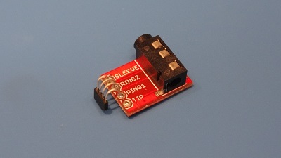
The following pics show the evolution of the v1 Alpha sensor housing for Holoseat. Holoseat uses a wheel speed sensor connected to a TRRS jack to detect user cadence and direction from a custom made tone ring.
| The sensor sub-assembly |
Getting the Base Sized
The first step was to size the base properly sized. It took a couple of passes to get the clearances worked out.
| First pass was a little small, second was a little loose | ||
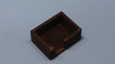
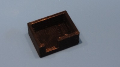
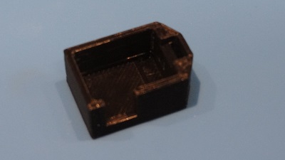
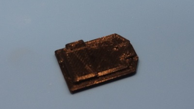
Developing the "Box"
The next step was to raise the walls of the base up to form a box. I had to include an opening in one of the walls to provide access to the jack. This fist time I forgot to bring the wall up to meet the jack, hence the second revision of the box.
| First pass at the box | ||
| Second pass at the box | ||
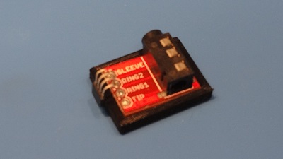
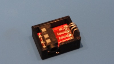
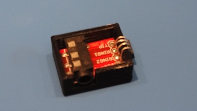
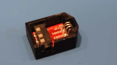
Enclosing the Sensor
Wrapping up the lower portion of the sensor enclosure required an extension to protect the sensor itself. Note its shape points in the direction of the sensor's face so users know how to place the completed sensor assembly.
| Box with a spot for the sensor | ||
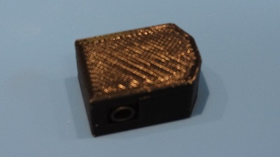
Adding a Top
All that was left was to create a top with a snug enough fit that it would stay in place without adhesive.
| And here is the top and the finished enclosure | ||
CAD Source Files/Assembly Instructions
Check the readme.txt files in the following folders. CAD models built in Fusion 360 and prototypes printed on PrintrBot Simple Metal.
- The "Box" - WSSM-03 - Sensor Housing Lower Half
- Top - WSSM-04 - Sensor Housing Upper Half
- Assembly Instructions
Images
01-SensorSubAssembly-sm.jpg (30.6 kB)
01-Base-FirstPass-sm.jpg (31.2 kB)
02-Base-SecondPass-sm.jpg (30.8 kB)
03-Box-FirstPass-sm.jpg (26.9 kB)
03b-Box-FirstPassWithSensor-sm.jpg (31.3 kB)
04-Box-SecondPass-sm.jpg (27.2 kB)
04b-Box-SecondPassWithSensor-sm.jpg (30.4 kB)
05-SensorSlot-sm.jpg (28.1 kB)
05b-SensorSlotWithSensor-sm.jpg (31.5 kB)
06-Top-sm.jpg (28.2 kB)
07-FinishedHousing-sm.jpg (32.6 kB)