Assembly Instructions v1.1
This is a newer document based on this one , and you should refer to that original version if you want to see the revision history.
Mechanical System
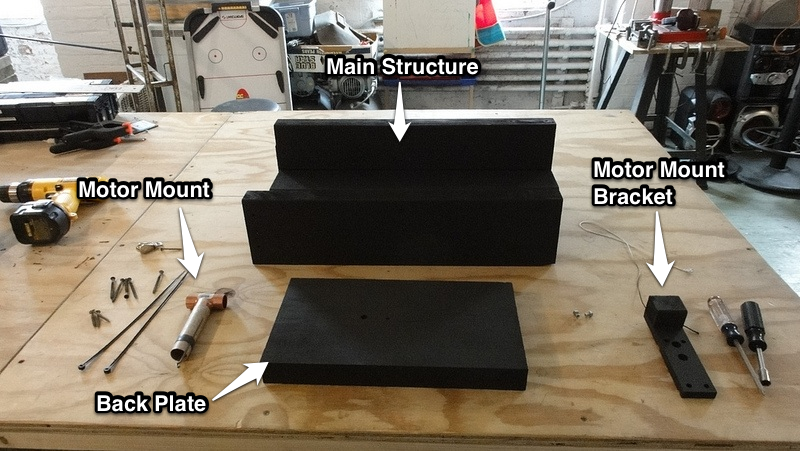
The assembly of the Mechanical System consists of four main sub-assemblies (shown in Figure 1 below):- The motor mount (a modified Estes D & E Engine Mount Kit)
- The motor mount bracket
- The main structure
- The back plate
Figure 1 - Shepard Mechanical Components
Notes
- Be sure to cut out the parts listed in CutList tab of the BOM
- The assembly process for the Mechanical System requires the ues of two different glues
- Wood Glue: Titebond II Premium Wood Glue - This glue forms tight bonds and dries very quickly. It should be used for all assembly steps except initial fin placement. It is particularly well suited to making fillets. Note, transfer this glue to small squeeze bottle for improved application.
- Multi-Surface Glue: Loctite Go2 Glue - This glue bonds to a variety of surfaces including metal, used to attach the copper t-connector to the card board Motor Mount
Motor Mount
Assembly of the motor mount follows the instructions supplied with the Estes D & E Engine Mount Kit with a few small exceptions which are required to accomodate the t-connector (MM06) used to vent the ejection charge.
- Take the mount tube (MM01) and mark one end as the front [where the motor will be inserted] and the other as the rear [where the t-connector (MM06) will be attached]
- Test fit the t-connector (MM06) in the mount tube (MM01) by inserting it approximately 1/4" into the mount tube (MM01) and then remove it; the fit will be tight, and may even require a slight stretching of the mount tube (MM01)
- Make a mark 1/4" from one end of the red engine block (MM04)
- Cut the red engine block (MM04) at the 1/4" line from the previous step, keeping the larger section as the final engine block (see Figure 2)
Figure 2 - Modified Engine Block (top) vs Original Engine Block (bottom) - Follow Step 1 in the Estes D & E Engine Mount Kit instructions
- Step 1.A - Make a mark on the mount tube (MM01) 1" from the rear, and make another mark 5/8" from the front [this second mark should be offset along the circumference of the mount tube (MM01) slightly]
- Step 1.B - Cut a 1/8" wide slit at the mark 1" from the rear of the mount tube (MM01); insert the engine hook (MM05) into the slit (see Figure 3)
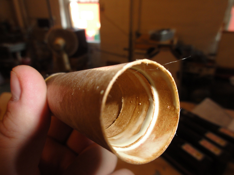
Figure 3 - Engine hook inserted into mount tube - Step 1.C - Apply wood glue to the outside of engine block (MM06) and the inside of the inside of the rear section of the mount tube (MM01) making sure to completely coat the inside of the mount tube (MM01) up to where the engine hook (MM05) is inserted; Slide the engine block (MM06) into the rear of the mount tube (MM01) until it rests agains the engine hook (MM05); be sure to smooth any excess glue in the mount tube (MM01) to create a smooth water tight surface (see Figure 4)
Figure 4 - Engine block inserted into mount tube
- Follow Step 2 in the Estes D & E Engine Mount Kit instructions - Apply a bead of wood glue around the mount tube (MM01) just to the rear of the mark 5/8" from the front and then slide the engine retainer ring (MM02) onto the the mount tube (MM01) from the front of the mount tube (MM01) until the engine retainer ring (MM02) is just past the 5/8" mark (see Figure 5)
Figure 5 - Engine retainer ring mounted - Allow the assembly to dry overnight
- Apply a bead of multi-surface glue to the edge of the base end of the t-connector (MM06)
- Insert the t-connector (MM06) into the rear of the mount tube (MM01) (see Figure 6)
Figure 6 - Completed motor mount - Allow the motor mount to dry over night
Motor Mount Bracket
- Prepare the plate (MMB01)
- Drill the four 1/4" through holes for the zip ties (MMB04) (see Figure 7)
Figure 7 - MMB01 with zip tie holes highlighted - Drill and counterbore the two 3/32" through holes for the machine screws (see Figure 8)
Figure 8 - MMB01 with machine screw holes highlighted - Create the two 1/4" dados on the bottom of the plate (MMB01) to provide space for the zip ties (MMB04); this can be done on a table saw with either a dado blade or with multiple passes using a standard 1/8" wide blade (see Figure 9)
Figure 9 - MMB01 with dados highlighted
- Drill the four 1/4" through holes for the zip ties (MMB04) (see Figure 7)
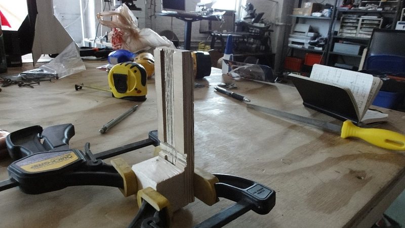
- Clamp the block (MMB02) to the rear edge of the plate (MMB01) (see Figure 10)
Figure 10 - Block clamped to plate - Drill pilot holes for the two 1-1/2" drywall screws
- Attach the block (MMB02) to the plate (MMB01) using two 1-1/2" drywall screws, making sure to leave approximately 1/8" of the rear screw exposed
Rail Shield
- Cut out the Rail Shield (RS03) from thin sheet metal (such as duct work metal)
- Fold down the long sides of the Rail Shield (RS03) per the dimensions listed in the CAD drawings; this will give the Rail Shield the required regidity
- Drill two mounting holes through the Rail Shield (RS03) per the CAD drawings
Main Structure
Figure 11 - Exploded Assembly View
- Assemble the Test Stand Base; Note: it is significantly easier to assemble the Test Stand Base using the concrete block (TSBa05) as a stand/jig
- Place the top (TSBa02) on the concrete block (TSBa05) so that the rear edge is flush with the concrete block (TSBa05)
- Place the two sides (TSBa01) along the edge of the concrete block (TSBa05) so the front edges of the sides (TSBa01) are flush with the front of the top (TSBA02)
- Clamp the sides (TSBa01) to the top (TSBa02)
- Drill pilot holes through the sides (TSBa01) into the top (TSBa02) [3 on each side], and use 2-1/2" dry wall screws (TSBa04) to attach the sides (TSBa01) to the top (TSBa02); be sure to remove the clamps
- Place the front (TSBa03) under the top so it rests against the concrete block (TSBa05)
- Drill pilot holes through the sides (TSBa01) [1 each side] and the top (TSBa02) [2 holes] into the front (TSBa03), and use 2-1/2" dry wall screws (TSBa04) to attach the front (TSBa03)
- Attach the Test Section Beam
- Remove the Test Stand Base from the concrete block (TSBa05)
- Draw a line down the centerline of the long axis of the top (TSBa02)
- Place and clamp the beam (TSBe01) along the line on the top (TSBa02)
- Turn the Test Stand Base on its side and drill 3 pilot holes through the top (TSBa02) and into the beam (TSBe01), and use the 2-1/2" dry wall screws (TSBe02) to attach the beam (TSBe01) to the top (TSBa02); be sure to remove the clamps
- Prepare the Back Plate
- Drill the 3/8" pass-through hole in the back plate (BP01)
- Place the Test Stand Base back on the concrete block (TSBa05)
- Place the back plate (BP01) against the back of the Test Stand Base [it should fit between the sides and rest against the concrete block (TSBa05) and the beam (TSBe01)]
- Drill 2 pilot holes through each side (TSBa01) into the back plate (BP01)
- Drill 1 pilot hole through the back plate (BP01) into the beam (TSBe01)
- Note: Do not attach the back plate (BP01) yet.
- Treat the test stand components with heat resistant paint
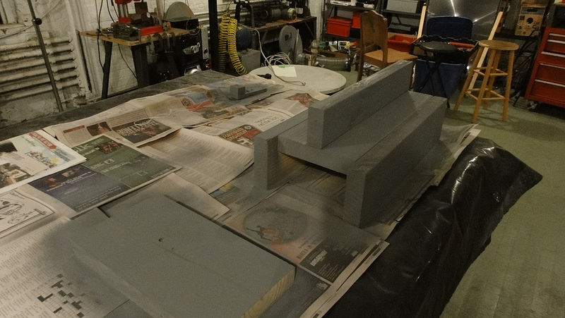
- In a well ventilated area, lay out all of the wooden components and apply two coats of heat resistent primer (see Figure 12)
Figure 12 - Priming Shepard components - Allow primer to dry per manufacture's instructions
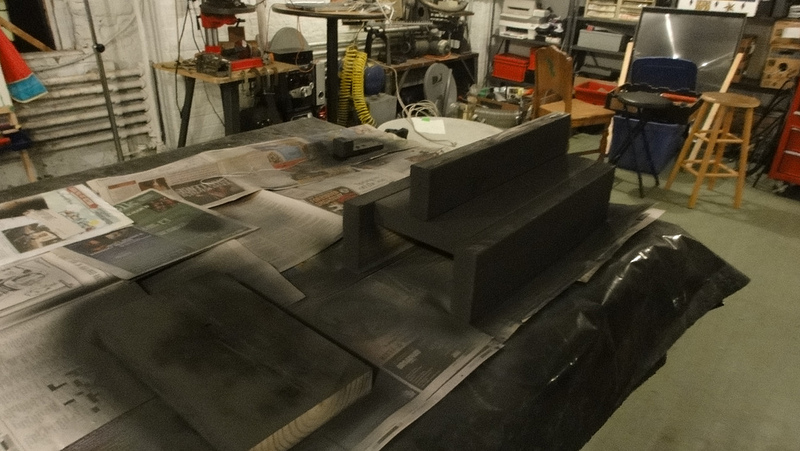
- Apply two coats of heat resistent paint (see Figure 13)
Figure 13 - Painting Shepard components - Allow paint to dry per manufacturer's instructions
- In a well ventilated area, lay out all of the wooden components and apply two coats of heat resistent primer (see Figure 12)
Final Assembly
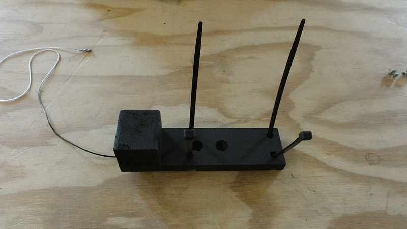
- Insert the two zip ties (MMB04) into the Motor Mount Bracket (see Figure 14)
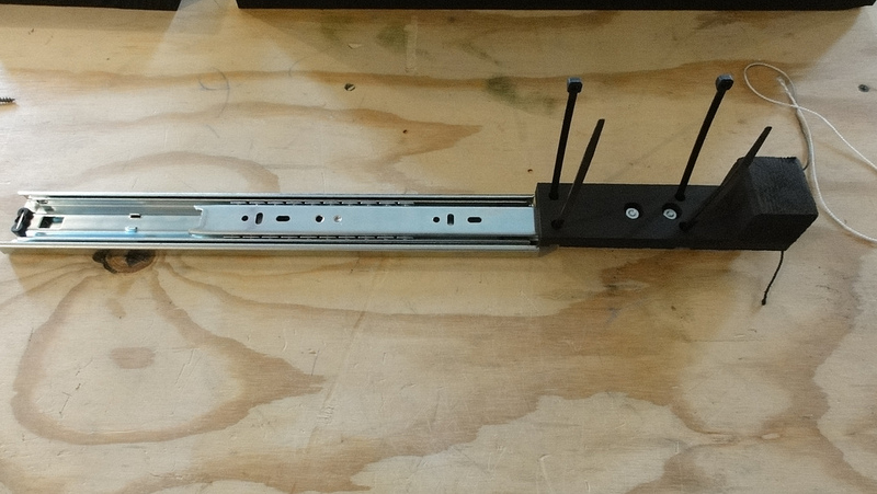
Figure 14 - Zip tie placement - Use the metal screws (MMB03) to attach the Motor Mount Bracket to the end of the drawer slide (RS01) (see Figure 15)
Figure 15 - Motor Mount Bracket attached to Drawer Slide - Use the metal screws (MMB03) to attach the Rail Shield (RS03) to the drawer slide (RS01) next to the Motor Mount Bracket. (not shown)
- Attach the drawer slide (RS01) to the beam (TSBe01) using 1-1/2" drywall screws (RS02) (see Figure 16)
Figure 16 - Drawer Slide attached to Beam - Place Motor Mount on Motor Mount Bracket and close the zip ties (MMB04) snuggly; note, be sure to have a motor in the motor mount to prevent the zip ties from crushing the Motor Mount (see Figure 17)
Figure 17 - Attaching the Motor Mount - Trim the excess portion of the zip ties (MMB04) (see Figure 18)
Figure 18 - Trimming zip ties - Place the Back Plate in position and attach it to the Test Stand Base with 2-1/2" drywall screws (BP03) (see Figure 19)
Figure 19 - Attaching the Back Plate - Attach the 1-1/2" dry wall screw (BP04) to the Back Plate just above the through hole leaving approximately 1/2" exposed; this screw is used to hang the small pulley (BP02)
- Use thin double-sided tape to attach the contact pad (MMB05) to the side of the motor mount block (MMB02) facing the back plate (BP01); note, be sure to align the contact pad with the Force Sensing Resistor mounting specified below
This completes the Mechanical System assembly process.
Data Acquisition (DAQ) System
The assembly of the DAQ system consists of three main sub-assemblies:- MAX31855 Thermocouple Amplifier Breakout Board
- Force Sensing Resistor (FSR) cable system
- Arduino ProtoShield
MAX31855 Thermocouple Amplifier Breakout Board
- The only assembly required for the MAX31855 breakout board is to solder the header pins and terminal block onto the board. Once this is done the breakout board can be soldered to the Arduino Protoshield.
Force Sensing Resistor (FSR) cable system
- The FSR came with male pins, which complicated assembly somewhat. It would be simpler to buy the version of the FSR with a female connector and make your cable fit that configuration. As it was, female D-SUB connectors that were on hand were used to connect the FSR to the CAT 5e cable that was used between the FSR and the ProtoShield. The pins were crimped on to two of the leads of the CAT 5e cable so that the female ends could receive the male pins of the FSR. The reason crimping was used instead of soldering for the pins is that it's very easy to melt the FSR's substrate, thus making the FSR useless, or at least severely altering its operation.
Arduino ProtoShield
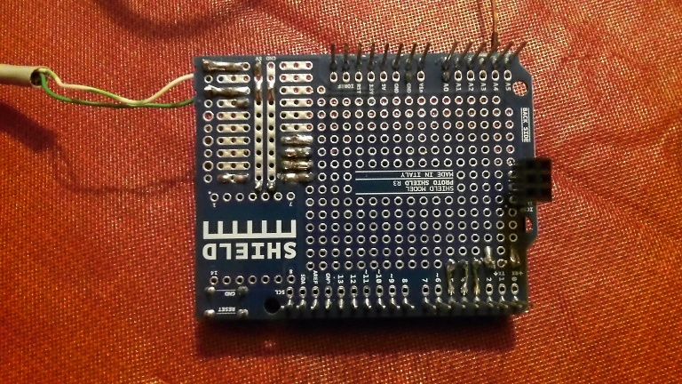
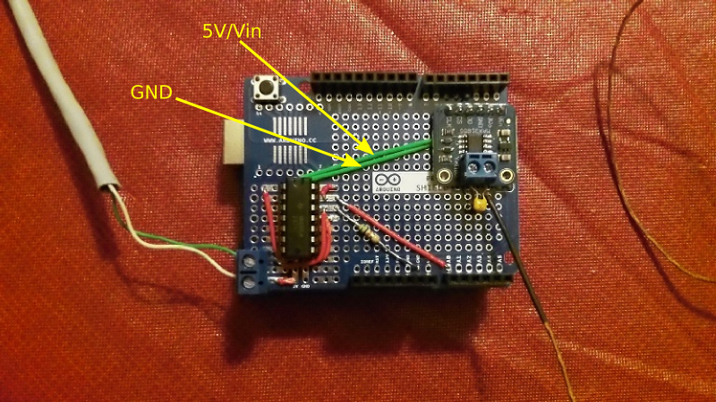
Components were soldered onto the ProtoShield in the configuration shown in the images below. Note that in the bottom view, the ProtoShield has been flipped vertically towards the bottom of the picture. This allows you to orient yourself so that you can follow the traces. For higher resolution images to aid in assembly, check the Shepard_v1.0_DAQ_Assembly_Images.zip file here
Figure 20 - Top View of the ProtoShield
- The MAX 31855 breakout board has the correct header pin spacing to fit the holes on the ProtoShield, so it was inserted directly. Note that the capacitor that is included with the K type thermocouple when purchased is being used. The thermocouple's reading had too much noise in it otherwise.
- The red and green wires used were breadboard prototyping jumpers from Radio Shack. Left over Ethernet cable wires can be used as well.
- The resistor was soldered directly to the ProtoShield, but care should be taken that the leads of the resistor do not short any of the connections on the board.
- A 14 pin DIP socket was used for the TLV2374 for multiple reasons including prevention of overheating of the IC during soldering, and ease of replacement in the event of damage due to a wiring mistake.
- A smaller screw terminal block for the FSR leads (left side) would have ideal, but the larger block pictured was all that was available at the time of assembly. The pins are spaced more widely on the block and thus the positioning was dictated by the spacing of the holes on the ProtoShield.
- Notice that even though the two green jumper wires disappear under the MAX 31855 breakout board in the image, they have been labeled with what pins they go from/to.
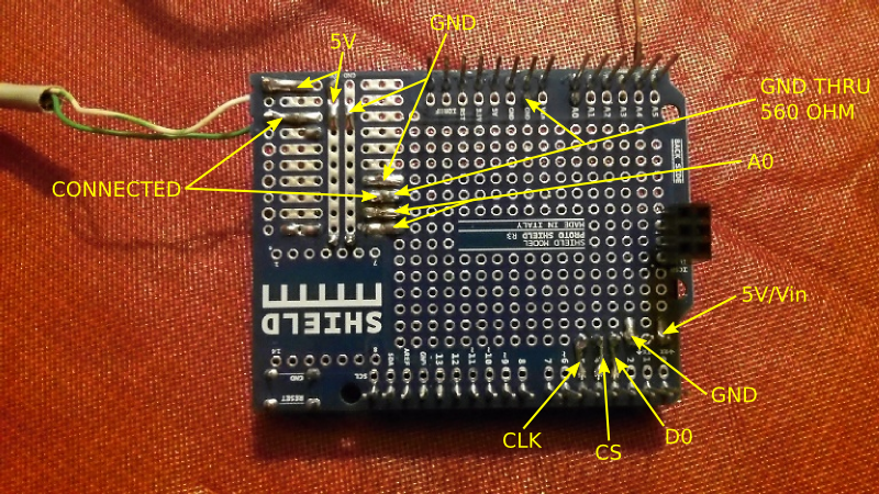
Figure 21 - Bottom View of the ProtoShield
- If you view the high resolution version of this image from the Shepard_v1.0_DAQ_Assembly_Images.zip file here , you'll notice that several solder bridges have been made to connect different points. Use the schematic diagram found in the Shepard_v1.0_DAQ.zip file here to give you a more complete view of what's being bridged.
- The solder bridges are made by laying short lengths of stripped solid wire against the pins (or in the holes) and then soldering them.
- Figure 22 labels what the corresponding top side connections are for most of the solder joints.
Figure 22 - Bottom View of ProtoShield With Landmark Connections
- The solder positions where the green and white/green wires are coming off the board is the location of the Force Sensing Resistor (FSR) screw terminal.