Assembly Instructions
Introduction
Below are the assembly instructions for the v0.3 Holoseat. The controller for this version is built using an AdaFruit Feather 32u4 Basic Proto. The sensors are on a remotely mountable board. Final assembly requires an appropriate set of under desk exercise pedals (we recommend DeskCycle or FitDesk ). Note, you will need to use your soldering skills on this build.
Sensor Board Assembly
Tools - Sensor Board
- Diagonal Cutters
- Wire Strippers
- Needle Nose Pliers
- Soldering Iron
- Punch Down Tool
Materials - Sensor Board
- (1) HS001 - Double-Side Prototype PCB
- (1) HS002 - Category 5e Jack
- (2) HS003 - 750 OHM 1/2W 1% Axial Resistor
- (2) HS004 - OH090U Hall Effect Sensor
- (2) HS005 - Diffused Blue 3mm LED
- Hook up wire
- Solder
Safety Issues - Sensor Board
- Care must be taken when using sharp hand tools to avoid cuts
- Care must be taken when using the soldering iron, the tip is very hot
- Always wear safety glasses while working with soldering irons
- Avoid breathing in the soldering fumes, use a vent or hood if needed to provide adequate ventilation
Product - Sensor Board
(1) Holoseat Sensor Board
Procedure - Sensor Board
- Prepare Sensor/LED sub-assemblies
Repeat this procedure twice to assemble (2) Sensor/LED sub-assemblies- Take (1) HS004 - OH090U Hall Effect Sensor and (1) HS005 - Diffused Blue 3mm LED from your supplies
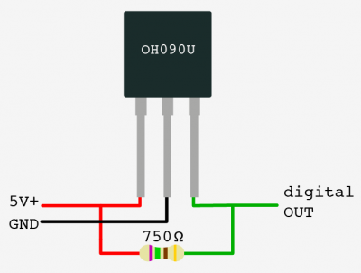
- Solder the LED's anode (long leg) to pin 3 of the sensor (the data pin) and solder the LED's cathode (short leg) to pin 2 of the sensor (the ground pin) using the following steps
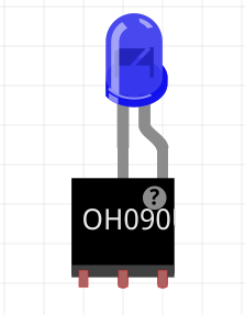
- Align the LED to it sits on top of the sensor with the long leg next to pin 3 and the short leg next to pin 2
- Wrap the LED's long leg around pin 3 to create a secure physical connection
- Wrap the LED's short leg around pin 2 to create a secure physical connection
- Apply solder to the two joints formed in the steps above to secure the connections between the LED and the sensor
- Cut approximately 40 cm lengths of black, red, and green hook up wire
- Strip both ends of the (3) lengths of hookup wire
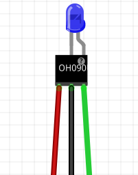
- Solder the hookup wire to the ends of the sensor pins (red to pin 1, black to pin 2, and green to pin 3) using the following steps
- Wrap one end of the red hook up wire around pin 1 to create a secure physical connection
- Apply solder to the joint formed in the step above to secure the connections between the red hookup wire and pin 1
- Wrap one end of the black hook up wire around pin 2 to create a secure physical connection
- Apply solder to the joint formed in the step above to secure the connections between the black hookup wire and pin 2
- Wrap one end of the green hook up wire around pin 3 to create a secure physical connection
- Apply solder to the joint formed in the step above to secure the connections between the green hookup wire and pin 3
- Apply sufficient heat shrink to the red and green joints to cover them completely
- Apply sufficient heat shrink to assembly to completely cover the solder joints of all three leads, leaving some overlapping the LED to give it strain releaf
- Apply larger heat shrink to the three leads made from the hookup wire to complete the Sensor/LED sub-assembly
- Take (1) HS004 - OH090U Hall Effect Sensor and (1) HS005 - Diffused Blue 3mm LED from your supplies
- Prepare the HS002 - Category 5e Jack
- Cut approximately 20 cm each of the following colors of hookup wire: (2) green, (1) red, (1) black
- Strip one end of each length of hookup wire
- Use a punch down tool to connect the hookup wires to their corresponding positions on the HS002 - Category 5e Jack for pinout option A
- Punch down the stripped end of the red hookup wire to Brown wire position of the Cat5e Jack
- Punch down the stripped end of the black hookup wire to Brown/White wire position of the Cat5e Jack
- Punch down the stripped end of a green hookup wire to Green wire position of the Cat5e Jack
- Punch down the stripped end of the other green hookup wire to Blue/White wire position of the Cat5e Jack
- Finish Assembling the Sensor Board
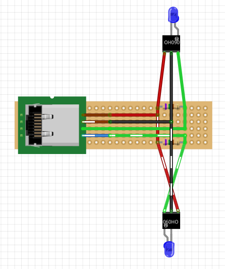
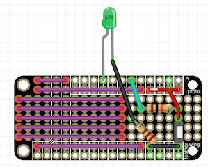
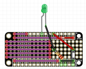
Reference the image below for the following steps- Connect the black leads
- Test fit the black leads from both Sensor/LED sub-assemblies and the HS002 - Category 5e Jack, cutting the wires to length as necessary (remember to leave room for the stripped wire)
- Strip the three black wires from the step above
- Position the three black wires above in the correct holes of the HS001 - Double-Side Prototype PCB and bend them over to create a secure physical connection
- Apply solder to the joint formed in the step above to secure the connection among the three black leads
- Connect the red leads
- Take the (2) HS003 - 750 OHM 1/2W 1% Axial Resistors and position them according to the diagram (making sure to bend their leads to secure them in place
- Test fit the red leads from both Sensor/LED sub-assemblies and the HS002 - Category 5e Jack, cutting the wires to length as necessary (remember to leave room for the stripped wire)
- Strip the three red wires from the step above
- Position the three red wires above in the correct holes of the HS001 - Double-Side Prototype PCB and bend them over to create a secure physical connection
- Cut a short length of red hookup wire to bridge the red leads according to the diagram
- Strip both ends of this additional length of red wire and place it according to the diagram, bending its ends over to create a secure physical connection
- Apply solder to the joint formed in the step above to secure the connection among the three red leads
- Connect each of the green leads
Repeat these steps for each of the sensors' green leads according to the diagram- Test fit the green leads from one of the Sensor/LED sub-assemblies and the HS002 - Category 5e Jack, cutting the wires to length as necessary (remember to leave room for the stripped wire)
- Strip the two green wires from the step above
- Position the two green wires above in the correct holes of the HS001 - Double-Side Prototype PCB and bend them over to create a secure physical connection
- Apply solder to the joint formed in the step above to secure the connection among the two green leads
- Cap the HS002 - Category 5e Jack
- Connect the black leads
The Sensor Board is now complete.
Controller Assembly
Tools- Controller
- Diagonal Cutters
- Wire Strippers
- Needle Nose Pliers
- Soldering Iron
- Punch Down Tool
Materials- Controller
- (1) HS002 - Category 5e Jack
- (1) HS007 - Adafruit Feather 32u4 Basic Proto
- (1) HS008 - 16mm Illuminated Pushbutton - Green Momentary
- (1) HS011 - 220 ohm 1/2W 5% Carbon Film Resistor
- Hook up wire
- Solder
Safety Issues- Controller
- Care must be taken when using sharp hand tools to avoid cuts
- Care must be taken when using the soldering iron, the tip is very hot
- Always wear safety glasses while working with soldering irons
- Avoid breathing in the soldering fumes, use a vent or hood if needed to provide adequate ventilation
Product- Controller
(1) Holoseat Controller
Procedure- Controller
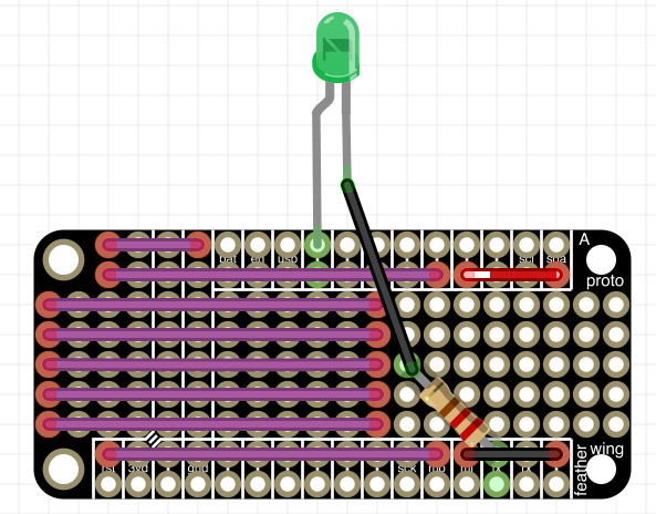
- Connect the HS008 - 16mm Illuminated Pushbutton - Green Momentary
- Prepare the HS008 - 16mm Illuminated Pushbutton - Green Momentary
- Cut approximately 20 cm each of the following colors of hookup wire: (1) green, (1) red, (2) black
- Strip both ends of all (5) lengths of hookup wire
- Physically connect one end of the black hookup wire to the (-) terminal of the HS008 - 16mm Illuminated Pushbutton - Green Momentary (this is the negative terminal of the embedded LED)
- Solder this joint to complete the connection
- Physically connect one end of a green hookup wire to the (+) terminal of the HS008 - 16mm Illuminated Pushbutton - Green Momentary (this is the positive terminal of the embedded LED)
- Solder this joint to complete the connection
- Physically connect one end of the black hookup wire to one of the remaining terminals of the HS008 - 16mm Illuminated Pushbutton - Green Momentary (this is one of the leads for the switch)
- Solder this joint to complete the connection
- Physically connect one end of the red hookup wire to one of the remaining terminals of the HS008 - 16mm Illuminated Pushbutton - Green Momentary (this is one of the leads for the switch)
- Solder this joint to complete the connection
- Connect the LED portion of the HS008 - 16mm Illuminated Pushbutton - Green Momentary
- Take (1) HS011 - 220 ohm 1/2W 5% Carbon Film Resistor and place it in the proto area of the HS007 - Adafruit Feather 32u4 Basic Proto, with one pin through a Ground hole and the other toward an edge of the proto area
- Solder these joints to complete the connection
- Take the black hookup wire connected to the (-) terminal of the HS008 - 16mm Illuminated Pushbutton - Green Momentary and put it through a hole next in the proto field next to the HS011 - 220 ohm 1/2W 5% Carbon Film Resistor
- Take the green hook up wire connected to the (+) terminal of the HS008 - 16mm Illuminated Pushbutton - Green Momentary and put it through the hole for pin 13 on the HS007 - Adafruit Feather 32u4 Basic Proto
- Solder these joints to complete the connection, making sure to bridge the black wire to the HS011 - 220 ohm 1/2W 5% Carbon Film Resistor
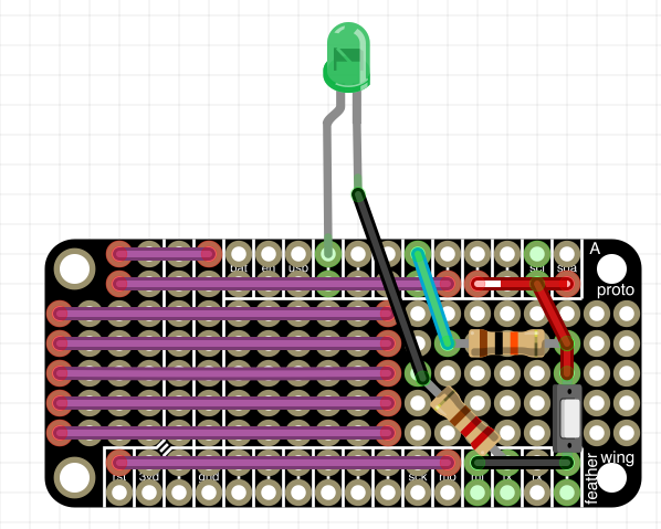
- Connect the switch portion of the HS008 - 16mm Illuminated Pushbutton - Green Momentary
- Insert the red hookup wire from the HS008 - 16mm Illuminated Pushbutton - Green Momentary into pin 10 (we will be using the built in pullup resistor, so we can simplify the wiring)
- Insert the remaining black hookup wire into a ground hole
- Solder these joints to complete the connection
- Prepare the HS008 - 16mm Illuminated Pushbutton - Green Momentary
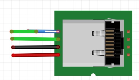
- Prepare the HS002 - Category 5e Jack
- Cut approximately 20 cm each of the following colors of hookup wire: (2) green, (1) red, (1) black
- Strip one end of each length of hookup wire
- Use a punch down tool to connect the hookup wires to their corresponding positions on the HS002 - Category 5e Jack for pinout option A
- Punch down the stripped end of the red hookup wire to Brown wire position of the Cat5e Jack
- Punch down the stripped end of the black hookup wire to Brown/White wire position of the Cat5e Jack
- Punch down the stripped end of a green hookup wire to Green wire position of the Cat5e Jack
- Punch down the stripped end of the other green hookup wire to Blue/White wire position of the Cat5e Jack
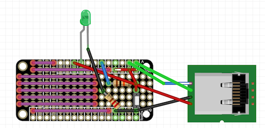
- Connect the HS002 - Category 5e Jack
- Insert the black hookup wire from the HS002 - Category 5e Jack into a ground hole
- Solder this joint to complete the connection
- Insert the red hookup wire from the HS002 - Category 5e Jack into USB hole
- Solder this joint to complete the connection
- Insert the green hookup wire connected to the Blue/White connection from the HS002 - Category 5e Jack into a pin 3
- Solder this joint to complete the connection
- Insert the other green hookup wire from the HS002 - Category 5e Jack into pin 2
- Solder this joint to complete the connection
- Cap the HS002 - Category 5e Jack
The Controller is now complete.
Holoseat Final Assembly
Tools - Holoseat Final Assembly
- none
Materials - Holoseat Final Assembly
- (1) Holoseat Sensor Board
- (1) Holoseat Controller
- (1) Exercise pedals (e.g DeskCycle or FitDesk )
- (1) HS006 - Cat5e cable
- (1) HS009 - USB cable
- (1) HS010 - 3/8 in dia. x 1/8 in thick magnet
- Cloth Tape (Gaf, duct, or similar)
- Computer
Safety Issues - Holoseat Final Assembly
- HS010 (magnet) is small, ensure children and animals do not accidentally swallow it
Product - Holoseat Final Assembly
(1) Completed Holoseat Final Assembly
Procedure - Holoseat Final Assembly
The primary objective for the final assembly is to mount the Sensor Board and the HS010 (magnet) on your chosen under desk exercise pedals. At this point in the development we are using easily reversible assembly processes (read tape) so we do not damage the exercise pedals. Note, for convenience these instructions show the Sensor Board and Controller mounted in small plastic containers (e.g. travel toothbrush holders or similar).
- Use the HS006 - Cat5e cable to connect the Sensor Board to the Controller
- Plug the Controller into the computer using the HS009 - USB cable, the sensor lights should both light up
- Place the Sensor Board on top the exercise pedals so the sensors can be placed along the path of the right hand bar of the pedals
- Tack in place with two strips of tape
- Place the sensors in position. Tacking them down with tape as needed. Be sure to mount them in the same orientation (e.g. the writing faces out for both sensors) to ensure they will both read the magnet as the sensors have a polarity.
The cadence sensor (connected to the Blue/White striped lead on the Sensor Board) should be placed ahead of the direction sensor (connected to the Green lead on the Sensor Board) when pedaling. This will be to the left if looking at the sensors from the side of the exercise pedals. Be sure both sensor are in the same arc of the pedal bar so they can both be triggered when the magnet is in place. - Place the HS010 - magnet on the right hand bar of the pedals in line with the arc of the two sensors (it should attach to the pedal bar through its magnetic field)
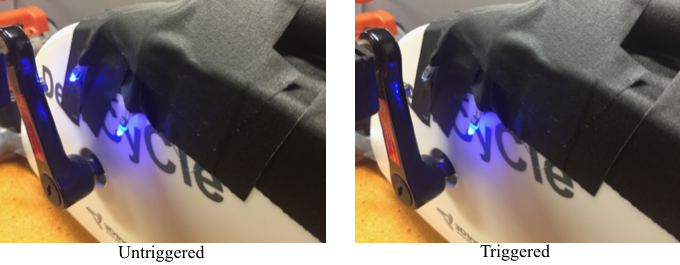
- Adjust the position of the sensors and HS010 - magnet such that each sensor is triggered (indicated by the light switching off as the pedal bar passes the sensor) one at a time (see image below)
If neither sensor is triggered try flipping the magnet over (in case of a polarity mismatch) or moving the magnet closer to the arc of the sensors (in case the magnet is beyond the range of the sensors). If both sensors are triggered at the same time try separating the sensors along the path of the arc. - Once the sensors and HS010 - magnet are in position, add sufficient tape to permanently mount the sensors and then the Sensor Board
The Holoseat Final Assembly is complete. Proceed to the Software Set Up instructions to install the firmware and desktop configuration app.