Index by title
Assembly Instructions
Introduction
TBD
Test Stand Body Assembly
Tools - Test Stand Body
- Mitre Saw (preferably powered)
- Pencil
- Carpentry square
- Tape Measure
- Screw Gun
- 1/16" Drill bit (for TS-07: 1-1/4" Fine Thread Drywall Screws)
- 1/8" Drill bit (for TSB-03:
#9 x 2-1/2" Coarse Thread Drywall Screws)
- Phillips screw driving bit
- (2) 12" (or larger) Bar clamps
- Sand paper
- Paint brush
- Painter's Tape
- Rags
Materials - Test Stand Body
- (2) TSB-01: Side Boards
- (2) TSB-02: Top Boards
- (6) TSB-03:
#9 x 2-1/2" Coarse Thread Drywall Screws
- (1) TSB-04: 36" Long 2x3 Board
- (1) TS-06: Nema 17 Stepper Motor Mount
- (4) TS-07: 1-1/4" Fine Thread Drywall Screws
- TSB-05: Semi-gloss latex paint
Safety Issues - Test Stand Body
- Always wear safety glasses when working with carpentry tools
- Take care when using saws (especially power saws)
Product - Test Stand Body
(1) TS-01: Holoseat Test Stand Body
Procedure - Test Stand Body
- Produce Side and Top Boards
- Use a miter saw to cut (2) 12" long boards from TSB-04: 36" Long 2x3 Board to produce (2) TSB-01: Side Boards
(also requires tape measure, carpentry square, and pencil)
- Use a miter saw to cut (2) 5" long boards from TSB-04: 36" Long 2x3 Board to produce (2) TSB-02: Top Boards
(also requires tape measure, carpentry square, and pencil)
- Assemble the TS-01: Holoseat Test Stand Body
- Use the bar clamps to secure (1) TSB-01: Side Boards and (1) TSB-02: Top Boards in a butt joint flush with the edge of the side board and with their ends aligned
- Drill (2) 1/8" pilot holes through the face of the side board and into the edge of the top board
- Use (2) TSB-03:
#9 x 2-1/2" Coarse Thread Drywall Screws to secure the side board to the top board
- Repeat the past 3 steps to attach the other TSB-02: Top Boards to the side board making sure the gap between the top boards is wide enough for the TS-06: Nema 17 Stepper Motor Mount
INSERT PIC HERE
- Place the TS-06: Nema 17 Stepper Motor Mount against the face of the side board between the top boards
- Drill (4) 1/16" pilot holes into the face of the side board
- Use (4) TS-07: 1-1/4" Fine Thread Drywall Screws to attach the motor mount to the side board making sure its top is flush with the top face of the top boards
INSERT PIC HERE
- Use the bar clamps to secure the other TSB-01: Side Boards to the opposite side of the (2) TSB-02: Top Boards
- Drill (2) 1/8" pilot holes through the face of the side board and into the edges of the top boards (1 hole in each top board)
- Use (2) TSB-03:
#9 x 2-1/2" Coarse Thread Drywall Screws to secure the side board to the top boards
INSERT PIC HERE
- Paint the Test Stand Body
- Lightly sand the new test stand body
- Wipe down the test stand body with a rag
- Use Painter's Tape to mask the TS-06: Nema 17 Stepper Motor Mount so it does not get paint on it during the next step
- Apply (2) coats of TSB-05: Semi-gloss latex paint to the faces of the test stand body per the paint's instructions
INSERT PIC HERE
Motor Assembly
Tools - Motor Assembly
#1 Phillips Screw Driver- Small files
- Blue painter's tape
Materials - Motor Assembly
- (1) MA-01: Adafruit Stepper motor - NEMA-17 size - 200 steps/rev, 12V 350mA
- (4) MA-02: M3 Screws
- (1) MA-03: Tone Ring Adapter
Safety Issues - Motor Assembly
- Take general safety precautions when using hand tools
Product - Motor Assembly
(1) TS-01: Holoseat Test Stand Body with TS-08: Motor Assembly attached
Procedure - Motor Assembly
- Place the TS-01: Holoseat Test Stand Body on its side to provide access to the underside of the TS-06: Nema 17 Stepper Motor Mount
- Place the MA-01: Adafruit Stepper motor into the slot in the motor mount with the wires from the stepper motor facing the gap between the motor mount and the test stand body
- Use the (4) MA-02: M3 Screws to attach the stepper motor to the motor mount
- Pull the wires from the stepper motor through the gap between the motor mount and the test stand body
- Place the TS-01: Holoseat Test Stand Body right side up
- Slide the MA-03: Tone Ring Adapter onto the stepper motor shaft, adjusting fit to the motor shaft and to tone rings as necessary using file/painter's tape
INSERT PIC
Tone Ring Controller
Tools - Tone Ring Controller
- Soldering Iron and stand
- Helping hands, etc
- Small punch
- Small flat screwdriver
#1 Phillips screwdriver
Materials - Tone Ring Controller
- (1) TS-01: Holoseat Test Stand Body
- (1) TRC-01: Arduino Uno
- (1) TRC-02: Adafruit Motor/Stepper/Servo Shield for Arduino v2.3 Kit (includes pins and jumper)
- (1) TS-02: Controller Mount (Arduino Bumper)
- (4) TS-15: Small Wood Screws (TBD)
- (1) TS-16: Power adapter (TBD)
- Solder
Safety Issues - Tone Ring Controller
- Care must be taken when using sharp hand tools to avoid cuts
- Care must be taken when using the soldering iron, the tip is very hot
- Always wear safety glasses while working with soldering irons
- Avoid breathing in the soldering fumes, use a vent or hood if needed to provide adequate ventilation
Product - Tone Ring Controller
(1) Holoseat Test Stand with support for Tone Ring Control
Procedure - Tone Ring Controller
- Solder the pins onto the motor shield from the TRC-02: Adafruit Motor/Stepper/Servo Shield for Arduino v2.3 Kit (see Installing Plain Headers for complete details) using the soldering iron, helping hands, and Arduino Uno
- Remove the shield from the Arduino
- Place the TRC-01: Arduino Uno in the TS-02: Controller Mount
- Place the Arduino/Mount sub-assembly on the TS-01: Holoseat Test Stand Body at one end of the top
INSERT PIC
- Mark locations for pilot holes using the small punch (deep enough to start the screws into)
- Attach the Arduino/Mount sub-assembly with the (4) TS-15: Small Wood Screws (TBD)
- Attach the motor shield onto the Arduino, ensuring it is firmly seated
- Attach the jumper to to VIN pins as shown below
- Wire the MA-01: Adafruit Stepper motor to the motor shield as shown in Using Stepper Motors
- Attach the TS-16: Power adapter (TBD) to the barrel jack of the Arduino Uno
 |
| Stepper Motor Wiring, credit Adafruit |
INSERT PIC
Sensor Controller Shield
Tools - Sensor Controller Shield
- Soldering Iron and stand
- Helping hands, etc
- Diagonal cutters
- Needle nose pliers
Materials - Sensor Controller Shield
- (1) SCS-01: Prototype Shield DIY KIT
- (1) SCS-02: TRSS Jack
- (4) SCS-03: Pins
- (2) SCS-04: 750 Ohm Resistor
- (1) SCS-05: LED
- (1) SCS-06: 220 Ohm Resistor
- Hookup wire
- Solder
Safety Issues - Sensor Controller Shield
- Care must be taken when using sharp hand tools to avoid cuts
- Care must be taken when using the soldering iron, the tip is very hot
- Always wear safety glasses while working with soldering irons
- Avoid breathing in the soldering fumes, use a vent or hood if needed to provide adequate ventilation
Product - Sensor Controller Shield
(1) SC-02: Sensor Controller Shield
Procedure - Sensor Controller Shield
- Solder the (4) SCS-03: Pins onto the SCS-02: TRSS Jack
- Solder the underside components onto the SCS-01: Prototype Shield DIY KIT
- Solder green hookup wire from pins 2 and 3 to their target locations according to the PCB diagram
- Solder the SCS-04: 750 Ohm Resistor to their positions according to the PCB diagram
- Solder black hookup wire to its position for the TRSS jack according to the PCB diagram
- Solder red hookup wire to its position for the TRSS jack according to the PCB diagram
INSERT PIC
- Solder the top side components onto the SCS-01: Prototype Shield DIY KIT
- Solder the TRSS Jack and pins sub-assembly to its position according to the PCB diagram
- Solder the SCS-05: LED to its position according to the PCB diagram
- Solder the SCS-06: 220 Ohm Resistor to its position according to the PCB diagram
- Solder red hookup wire to its position from the LED to pin 13 according to the PCB diagram
INSERT PIC
Sensor Controller
Tools - Sensor Controller
- Small punch
#1 Phillips screwdriver
Materials - Sensor Controller
- (1) TS-01: Holoseat Test Stand Body
- (1) SC-01: Arduino Uno
- (1) SC-02: Sensor Controller Shield
- (1) TS-02: Controller Mount (Arduino Bumper)
- (4) TS-15: Small Wood Screws (TBD)
Safety Issues - Sensor Controller
- Take general care when working with carpentry tools
Product - Sensor Controller
(1) Holoseat Test Stand with support for Tone Ring and Sensor Control
Procedure - Sensor Controller
- Place the SC-01: Arduino Uno in the TS-02: Controller Mount
- Place the Arduino/Mount sub-assembly on the TS-01: Holoseat Test Stand Body next to the TS-04: Tone Ring Controller making sure to offset the placement so the TS-13: TRSS Cable will fit into the jack on the sensor controller when it is completed
- Mark locations for pilot holes using the small punch (deep enough to start the screws into)
- Attach the Arduino/Mount sub-assembly with the (4) TS-15: Small Wood Screws (TBD)
- Attach the TS-13: TRSS Cable into the TRSS jack on the SC-02: Sensor Controller Shield
- Attach the SC-02: Sensor Controller Shield onto the Arduino, ensuring it is firmly seated
INSERT PIC
Final Assembly
Tools - Final Assembly
- Rubbing alcohol
- Cotton balls
Materials - Final Assembly
- Test Stand
- (1) TS-09: Sensor Mount
- (1) TS-10: Adhesive Tape Square
- (1) TS-11: USB Hub
- (2) TS-12: USB Cables
- (1) TS-14: Holoseat Controller Mount
- (1) TS-16: Power adapter
- (8) TS-19: Command Strip Medium Picture Hanging Strips
Safety Issues - Final Assembly
Product - Final Assembly
Completed Test Stand
Procedure - Final Assembly
- Use (1) TS-12: USB Cable to connect the tone ring controller to the TS-11: USB Hub
- Plug the TS-16: Power adapter into the barrel connector of the tone ring controller
- Use (1) TS-12: USB Cable to connect the sensor controller to the TS-11: USB Hub
- Use rubbing alcohol, cotton balls, and the (8) TS-19: Command Strip Medium Picture Hanging Strips to attach the TS-14: Holoseat Controller Mount to the opposite end of the test stand body from the controllers per the command strip instructions
- Use the TS-10: Adhesive Tape Square to attach the TS-09: Sensor Mount adjacent to the position of the tone ring (when attached)
INSERT PIC
Resources
Holoseat Test Stand
Instructions
Design Data
Research
Software Source Code
Firmware
Common
| Field |
Value |
| Baud Rate |
57600 |
| Data Bits |
8 |
| Parity |
None |
| Stop Bit |
1 |
Commands are sent as JSON strings with a message ID (may be an empty string, but must be present), a URI, an HTTP verb, and possibly arguments.
Direction of 1 means CW and -1 means CCW.
Tone Ring Controller
| Command Name |
URI |
Verb |
| Run the motor |
/motor |
PUT |
|
{"messageId":"1000","uri":"/motor","verb":"PUT", "args":{"revolutions":1, "cadence": 30, "direction":1}} |
|
{messageId":"1000","revolutions":1, "cadence": 29, "CW":1} |
|
Sensor Controller
| Command Name |
URI |
Verb |
| Get the sensor stats |
/stats |
GET |
|
{"messageId":"1000","uri":"/stats","verb":"GET"} |
|
{messageId":"1000","poles":18, "maxCadence": 30, "direction":1} |
|
| Clear the sensor stats |
/stats |
DELETE |
|
{"messageId":"1000","uri":"/stats","verb":"DELETE"} |
|
{messageId":"1000","poles":0, "maxCadence": 0, "direction":0} |
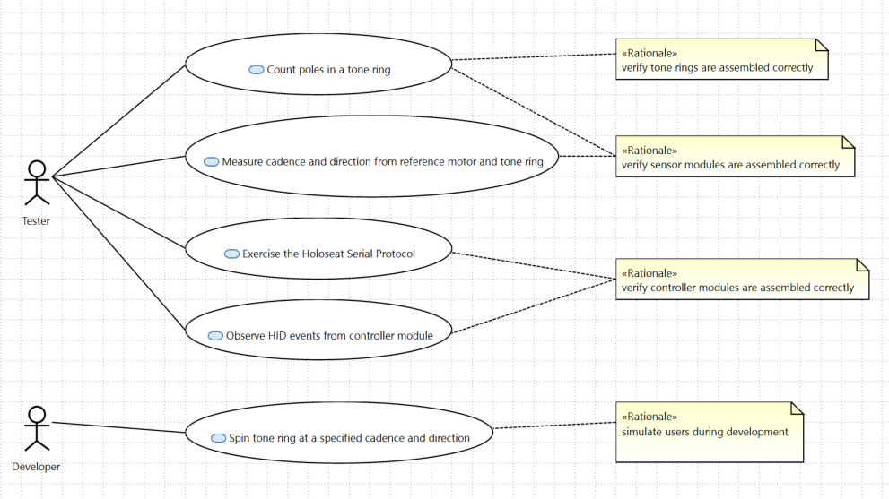
Holoseat Test Stand User Stories
Introduction
The following Use Case diagram documents the user stories for the Holoseat Test Stand. You can read the diagram in the pattern of agile user stories using the following guide:
"As a <<actor name>> I want to <<use case>> so that I can <<rationale>>."
| Element |
Description |
| <<actor>> |
Name under the stick figures |
| <<use case>> |
Text in the ovals |
| <<rationale>> |
Text in the comment blocks labeled <<Rationale>> |
User Stories
Vendor Documentation
Arduino USB PIDs
The Holoseat Test Stand uses Arduino boards to interface with the motor and sensor. The USB VID and PID are required by the Holoseat serial library used to connect to these boards to ensure it only queries the appropriate devices for the presence of the test stand firmware. The following list covers the VIDs and PIDs for all boards Model B has access to for purposes of building test stands.
Adafruit Components
Holoseat Test Stand
The Holoseat Test Stand is a development and manufacturing resource for Model B's Holoseat. Developers can use it to simulate user activities in predictable and repeatable testing. And the manufacturing team can use the test stand to verify the key sub-systems (sensor, tone ring, and controller) are assembled correctly and work according to their specifications.
Key resources for the test stand are: