Forums » Discussion »
Engine Mount Requirements
Added by Christopher Sigman almost 11 years ago
As a result of one of the places that the discussion that took place and was posted to a news post today, it seemed prudent to talk about what the design requirements are for the engine mount for Shepard (v2 I suppose). Below is a list of some of the requirements as I see them thus far. Feel free to reword/scratch/add, and challenge any assumptions I've made.
- Shall connect to the load sensor
- Shall prevent movement of the engine undergoing testing
- Shall have the ability to mount an Estes 1/4A engine
- Shall have the ability to mount an Estes engine which has a purported maximum thrust output less than the maximum range the load sensor can measure
- Shall handle catastrophic failure of the engine being tested without damage
- The engine mount shall be able to be used without a reduction of other requirements after a catastrophic engine failure
- The resistance of the engine mount to catastrophic failure shall be at least proportional to the maximum output of an Estes motor that reaches the maximum measurement range of the load sensor.
Replies (8)
RE: Engine Mount Requirements - Added by Christopher Sigman almost 11 years ago
A few discussion points based upon those "requirements" I've laid out.
3 and 4 show that the mount must be adjustable to hold different diameter/length engines. I'm assuming this makes more sense than having a 54mm inner diameter mount with adapters for various other sized engines.
5 and 6 do not mean the same thing. The purpose of 5 is to illustrate that an engine failure should not turn the engine mount into shrapnel, whereas 6 is perhaps a nice-to-have.
Is 6 a nice-to-have, or a legit requirement?
This doesn't specify how the mount should handle a catastrophic engine failure, and purposefully so. One of the things that I've been thinking about is that one of the easiest to manufacture mount designs that meets these requirements might not contain the fallout from the failure to the long axis of the engine, and may not need to. If this isn't the case though, it can certainly be revised.
I don't quite like the wording I provided for 7, but I couldn't find a better way to say it. It's sort-of covered by 5/6, but not entirely.
RE: Engine Mount Requirements - Added by Aaron Harper almost 11 years ago
#1 Do we need to specify that, since no reading is possible without connecting it to the sensor?
#2 Makes sense.
#3 has a low return and high effort. I can only justify testing A-E motors which have 18mm and 24mm bodies. There are commercial adapters allowing A-C motors to fly 24mm rockets, and the difference in the D and E motors is length, and an adapter (a ring spacer) can be supplied. At about a 1/4 sec burn time, they are not a good demonstration of the technology and have a 13mm diameter body. http://exploration.grc.nasa.gov/education/rocket/rktenglab.html
#4 is not a problem. The sensor is able to handle up to and including an E, the largest motor Estes makes.
#5 is a tall order, and may prove impossible to test. It should read that the mount may be damaged, but must remain in ine piece and attached to the test stand.
#6 is an even taller order. It may be impossible to detect fine variations if the mount built heavily enough to completely shrug off the detonation of an E class motor. This is due to the increased energy necessary to move a larger mass.
#7 I am not entirely sure where you are headed with this. Is this a restating of #4?
RE: Engine Mount Requirements - Added by Christopher Sigman almost 11 years ago
- It's only there because in my experience someone won't see the obvious. It's become habit to (try to) put the obvious in requirements.
- I'm fine with changing it to be that the min is A motors
- Of note: Estes in fact does make larger motors than E's (F's and G's): http://www.estesrockets.com/rockets/engines/pro-series-ii-motors . Some of those are 50N engines, which would be in the range of the load sensor if I'm not mistaken.
- I like your wording better here.
- This one may in fact be a nice-to-have, and we can de-scope it. The tricky thing I think is going to be testing it.
- I'll get rid of this one... the more I think about it, the more I think it's not necessary to specify what I was thinking.
RE: Engine Mount Requirements - Added by Christopher Sigman almost 11 years ago
- Shall connect to the load sensor
- Shall prevent movement of the engine undergoing testing
- Shall have the ability to mount an Estes A engine
- Shall have the ability to mount an Estes engine which has a purported maximum thrust output less than the maximum range the load sensor can measure
- Shall handle catastrophic failure of the engine being tested while remaining in one piece attached to the test stand.
- The engine mount may be able to be used without a reduction of other requirements after a catastrophic engine failure
RE: Engine Mount Requirements - Added by J. Simmons almost 11 years ago
Just a quick reminder that some of this should have already been covered by the project requirements (also check out the old forum discussions and meeting minutes on requirements).
If I recall correctly, one of the big things that came out of the design discussion for the first generation motor mount is wanting to produce something that was safe (that is would prevent the motor from escaping the test stand and something that would not produce shrapnel) while following NAR guidelines for model rocket construction as much as possible (in the hope that we would be able to get their support/endorsement for Shepard down the road). This is how we ended up using an Estes motor mount for a D/E motor as the basis of the Shepard motor mount (safe, reliable, already NAR approved).
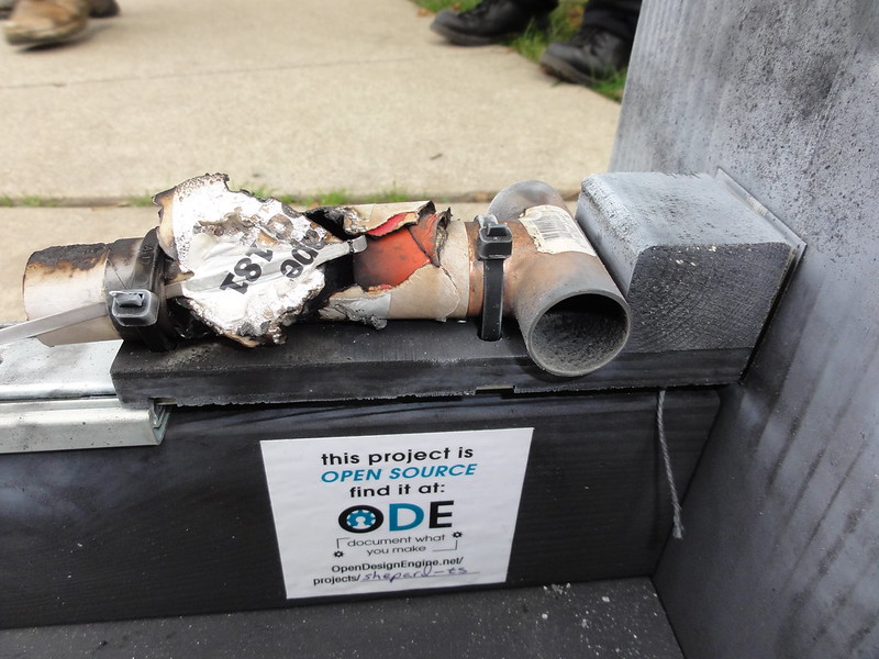
Unfortunately, it takes some time to assemble it, and as was shown during the Ft Wayne Maker Faire, if a motor fails, the motor mount must be replaced. From an operations standpoint, motor failures requiring significant repairs or backup components is pretty undesirable. In the case of the Maker Faire, the failure happened toward the end of day 1 of 2, and without spare motor mounts, we had to end our demos prematurely.
If you go back and look at the completed Shepard motor mount assembly, the Estes motor mount is attached to the test stand with two 50 lbf zip ties. It turns out these zip ties were unharmed by the motor failure (see below).
This got me thinking. What if we just hold the motor onto a flat plate with U-Bolts in place of the zip ties? We could place movable raised stops on the plate to hold the motor in position horizontally (this would replace the clip in the Estes motor mount), and use wing nuts on the U-bolts so motors could be quickly inserted and removed. This design has the following advantages:
- No elements enclose the motor, so motor failure does not produce any non-card board shrapnel
- Easy to switch out motors, just loosen two pair of wing nuts, remove motor, insert motor, tighten wing nuts
- No motor adapters required, we just move the stops to adjust for motor length, and tighten the U-bolts down more for smaller diameter motors (or possibly swap out the U-bolts)
If we permanently mount the temp sensor, we could adjust the location of the sensor relative to the motor by having different positions for the stops for different motors based on where we need to take the temperature reading on the motor in question.
One final comment on requirements. I believe we will find that calibration is something that is done before most firings (certainly as part of setup). As a training and education tool, I expect many users will run calibrations more frequently than in standard operations might ordinarily require. After all, most lab classes (physics, chemistry, etc) start off with lab assignments where the students calibrate their instruments (scales, thermometers, etc). So, I would encourage the team to make a new requirement that calibration be possible without any configuration changes to the test stand (such as removing the motor mount).
RE: Engine Mount Requirements - Added by Jeremy Wright almost 11 years ago
A few things:
- Chris had an idea for the motor mount design somewhere (maybe on Google+) that I haven't been able to find again. I was having a hard time visualizing his idea, and so haven't given it proper consideration.
- I like J's concept for the most part, but have a few suggestions/thoughts.
- I would not suggest mounting a round (cylindrical) motor down to a flat plate. It's better to clamp a round object in a v-block. The U-bolts could still be used with the V-block. Aaron has suggested this elsewhere (email or G+ I think).
- I like the idea of using wing nuts for quick changes, but want to make sure the final design does in fact use the end stop to keep the motor from launching and not the U-bolts. It will be harder to repeatably set the torque on a wing nut, and so you could be skewing your test results by deforming a motor differently each time you attach one. The balance between holding the motor in place and deforming it would have to be found, and then the U-bolts would have to be torqued to that before each test. Using the U-bolts only to keep the motor going straight against the end stop (as J has suggested I think) is the way to go for this concept.
- From what I've heard, Misumi has an engineering applications department. It's likely that they would have something that would work, and since we're looking at using they're extruded aluminum for Shepard kits, they should be willing to help us. They may have some handy dandy thing that meet all of our motor mounting requirements with a minimal amount of manufacturing.
I'm not opposed to there being design discussions on Google+ (or other social media), but I personally would prefer if we make ODE the hub and central repository for documentation. One way to do that is to post things to ODE first, and link to them in G+/FB/whatever with a teaser image. There have been a few threads lately that I've had trouble finding again because I couldn't remember whether they started on email, G+ or ODE, and copying a long discussion that originated on G+ to ODE is not ideal.
RE: Engine Mount Requirements - Added by Jeremy Wright almost 11 years ago
Oh, and I also agree with J that the stand needs to make it convenient to calibrate.
RE: Engine Mount Requirements - Added by Aaron Harper almost 11 years ago
Slightly off topic... I found a simple circuit that would let an arduino or Beaglebone light off the engine under test while maintaining safety: http://www.w6pql.com/high_current_solid-state_dc_switch.htm
(1-8/8)